Passive Components Blog
No Result
View All Result
  • Home
  • NewsFilter
    • All
    • Aerospace & Defence
    • Antenna
    • Applications
    • Automotive
    • Capacitors
    • Circuit Protection Devices
    • electro-mechanical news
    • Filters
    • Fuses
    • Inductors
    • Industrial
    • Integrated Passives
    • inter-connect news
    • Market & Supply Chain
    • Market Insights
    • Medical
    • Modelling and Simulation
    • New Materials & Supply
    • New Technologies
    • Non-linear Passives
    • Oscillators
    • Passive Sensors News
    • Resistors
    • RF & Microwave
    • Telecommunication
    • Weekly Digest

    Würth Elektronik Expands Nanocrystalline Cable Cores for Broadband EMI Suppression

    High‑Speed Supercapacitor Balancing for AI Data Center Power Systems

    Bourns Introduced Automotive TVS Diodes for Compact ESD Protection

    EMC‑Compliant PCB and Connector Design Guidelines

    Practical Value of Structural Diagnostics for Tantalum Capacitor Anodes

    Hall-Effect Sensing for Harsh Environments: TT Electronics Selected in NASA’s Dragonfly Fan

    Bourns Releases Automotive Gate Driver Transformer for Isolated Power

    Stackpole Releases High-Frequency Thin Film Chip Resistors for RF up to 50 GHz

    Knowles Expands High‑Q Ceramic Core Inductors for RF designs

    Trending Tags

    • Ripple Current
    • RF
    • Leakage Current
    • Tantalum vs Ceramic
    • Snubber
    • Low ESR
    • Feedthrough
    • Derating
    • Dielectric Constant
    • New Products
    • Market Reports
  • VideoFilter
    • All
    • Antenna videos
    • Capacitor videos
    • Circuit Protection Video
    • Filter videos
    • Fuse videos
    • Inductor videos
    • Inter-Connect Video
    • Non-linear passives videos
    • Oscillator videos
    • Passive sensors videos
    • Resistor videos

    EMC‑Compliant PCB and Connector Design Guidelines

    Why Isolated DC/DC Power Supplies Fail Late, Würth Elektronik Podcast

    Designing 800 V DC EMC Filters: Calculation, Simulation and Measurement

    Current Sense Transformer Datasheet and Design‑in Guide

    Designing a USB Type‑C Flyback Planar Transformer with Frenetic’s Planar Tool

    Magnetics Design in High‑Frequency GaN Converters

    Qi2 Wireless Charging: Inductors, Capacitors and EMC Filters

    Two‑capacitor paradox explained for engineers

    Capacitances of Nonlinear MLCCs: What Datasheets Don’t Tell You

    Trending Tags

    • Capacitors explained
    • Inductors explained
    • Resistors explained
    • Filters explained
    • Application Video Guidelines
    • EMC
    • New Products
    • Ripple Current
    • Simulation
    • Tantalum vs Ceramic
  • Knowledge Blog
  • DossiersNew
  • Suppliers
    • Who is Who
  • PCNS
    • PCNS 2025
    • PCNS 2023
    • PCNS 2021
    • PCNS 2019
    • PCNS 2017
  • Events
No Result
View All Result
Passive Components Blog
No Result
View All Result

Vishay Releases Sulfur‑Resistant Chip Resistors

12.2.2026
Reading Time: 6 mins read
A A

Vishay’s new RCA‑SR e3 series are AEC‑Q200 qualified thick film chip resistors designed for sulfur‑rich and thermally demanding environments in automotive, industrial, and telecom electronics.

By combining proven sulfur resistance with tight long‑term stability, they target design engineers who struggle with latent field failures caused by sulfur contamination and drift in standard thick film parts.

RelatedPosts

Vishay Unveils 1.5 kV IHDV High Voltage Power Inductors for EV and Industrial Converters

Vishay Extends Automotive Ferrite Beads for High‑Current EMC Noise Filtering

Vishay Releases High‑Current Radial Inductors up to 209 A

Key features and benefits

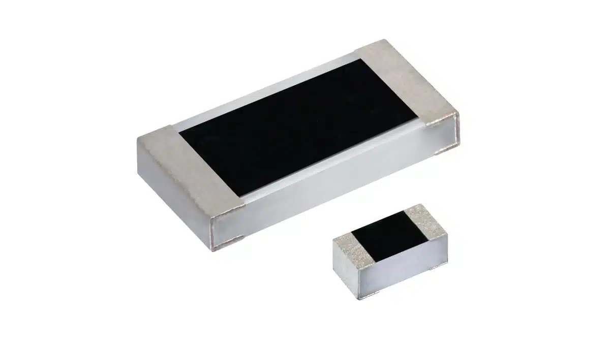
The RCA‑SR e3 thick film chip resistors family is positioned as a standard thick film chip platform with enhanced sulfur resistant resistors for applications exposed to polluted air, rubber and fuel vapors, or industrial atmospheres. The series is qualified to AEC‑Q200, making it suitable for automotive control units and other high‑reliability electronics where component derating and long service life are critical.

Key characteristics include:

  • Sulfur withstand capability tested per ASTM B809‑25, maximum resistance drift of 1% after 1000 h at 60 °C, addressing failure modes in sulfur‑containing atmospheres where conventional silver‑based terminations can corrode and go open.
  • Long‑term stability with ΔR/R ≤ 1% after 1000 h at rated power at 70 °C, helping maintain calibration and accuracy over equipment lifetime.
  • Standard thick film construction with a protective coating for electrical, mechanical, and climatic protection, supporting robust performance under vibration, temperature cycling, and humidity.
  • RoHS‑compliant and halogen‑free design, simplifying environmental compliance for global platforms.
  • Pure matte tin terminations compatible with both lead‑free and legacy lead‑containing soldering processes, easing second‑source and redesign scenarios.

For purchasing teams, the fact that RCA‑SR e3 is framed as a standard thick film series with added sulfur robustness means it can be treated as a drop‑in improvement over conventional chips in many BOMs, rather than as a niche specialty resistor.

Typical applications

Sulfur‑resistant chip resistors are relevant wherever electronics operate near combustion, rubber, fuels, or industrial emissions. The RCA‑SR e3 series is positioned for automotive, industrial, and telecommunications equipment that must remain stable over long field lifetimes.

Typical use cases include:

  • Automotive ECUs and sensors mounted in the engine compartment or underbody, exposed to exhaust gases and road pollution.
  • Industrial control systems in refineries, chemical plants, or rubber processing lines where airborne sulfur compounds are present.
  • Telecommunications infrastructure installed near roads or industrial areas, where long‑term stability and low drift reduce maintenance visits.
  • General purpose signal conditioning, pull‑ups, voltage dividers, and bias networks where latent sulfur‑induced opens would be costly or difficult to diagnose.

In many of these applications, the main value of a sulfur‑resistant series is not a visible performance boost, but reduced field failures and fewer unplanned service events over the product lifetime.

Technical highlights

The RCA‑SR e3 family spans five popular chip sizes and covers a broad resistance range, making it easy to design in across different power and voltage levels.

Case sizes and ratings

  • Available case sizes: 0201, 0402, 0603, 0805, 1206.
  • Power ratings at 70 °C (P70):
    • RCA0201‑SR e3: 0.05 W.
    • RCA0402‑SR e3: 0.1 W.
    • RCA0603‑SR e3: 0.125 W.
    • RCA0805‑SR e3: 0.25 W.
    • RCA1206‑SR e3: 0.25 W.
  • Maximum operating voltage:
    • 0201: 30 V.
    • 0402 and 0603: 75 V.
    • 0805: 150 V.
    • 1206: 200 V.
  • Operating temperature range: -55 °C to +155 °C.

In practice, the combination of -55 °C to +155 °C and AEC‑Q200 qualification allows these parts to be used in automotive and industrial designs that face aggressive thermal cycling, provided standard derating guidelines from the manufacturer datasheet are observed.

Resistance range, tolerance, and TCR

  • Resistance range:
    • RCA0201‑SR e3: 10 Ω to 1 MΩ; jumper (0 Ω).
    • RCA0402‑SR e3, RCA0603‑SR e3, RCA0805‑SR e3, RCA1206‑SR e3: 10 Ω to 10 MΩ; jumper (0 Ω).
  • Resistance tolerances: ±1% and ±5%.
  • TCR options:
    • 0201: ±200 ppm/K.
    • 0402, 0603, 0805, 1206: ±100 ppm/K and ±200 ppm/K.

For many control and sensing circuits, ±100 ppm/K is sufficient to keep temperature‑induced error within a few tenths of a percent over a wide temperature swing, while ±200 ppm/K is adequate for less critical pull‑up and biasing roles. According to the manufacturer’s datasheet, designers should select the appropriate TCR and tolerance combination based on the total error budget of their analog or mixed‑signal chain.

Design‑in notes for engineers

When considering a switch from standard thick film chips to sulfur‑resistant devices like RCA‑SR e3, the main design‑in effort is usually at the footprint and derating level rather than circuit topology. Because the series uses mainstream case sizes and power ratings, many existing 0201–1206 pads can be reused if the designer confirms the land pattern against the manufacturer’s recommended footprint.

Practical design‑in recommendations:

  • Use sulfur‑resistant types in positions exposed to air exchange or external pollution, such as near connectors, vents, or on boards placed in engine compartments or industrial cabinets with air circulation.
  • Pay attention to the specified operating voltage and power rating; in high‑voltage dividers or line‑connected sensing, select 0805 or 1206 parts and follow the derating curves from the datasheet instead of operating at the absolute maximum values.
  • Where long‑term calibration is important (current shunts for low current ranges, precision dividers for ADC reference scaling), prefer the ±1% tolerance and ±100 ppm/K TCR options where available.
  • For jumpers (0 Ω), check the recommended current and power limits in the official documentation, as these are often constrained by track width and thermal behavior rather than the nominal “0 Ω” label.
  • In automotive designs targeting AEC‑Q200, document the alignment between the component’s qualification and the system‑level environmental test plan, especially for sulfur exposure and long‑term drift.

From a supply‑chain perspective, consolidating on a sulfur‑resistant series like RCA‑SR e3 can simplify global product platforms, since the same BOM can be used in both benign and sulfur‑rich markets without separate variants dedicated to harsh environments.

Source

This article is based on an official Vishay Intertechnology press release and associated product information for the RCA‑SR e3 sulfur‑resistant thick film chip resistor series, with additional commentary aimed at design and purchasing engineers.

References

  1. Vishay press release – Vishay Intertechnology Standard Thick Film Chip Resistors Combine Sulfur Resistance With Long Term Stability (RCA‑SR e3)
  2. Vishay RCA‑SR e3 product page

Related

Recent Posts

Würth Elektronik Expands Nanocrystalline Cable Cores for Broadband EMI Suppression

23.6.2026
3

Bourns Introduced Automotive TVS Diodes for Compact ESD Protection

23.6.2026
4

Hall-Effect Sensing for Harsh Environments: TT Electronics Selected in NASA’s Dragonfly Fan

22.6.2026
20

Bourns Releases Automotive Gate Driver Transformer for Isolated Power

22.6.2026
16

Stackpole Releases High-Frequency Thin Film Chip Resistors for RF up to 50 GHz

19.6.2026
10

Knowles Expands High‑Q Ceramic Core Inductors for RF designs

19.6.2026
20

Vishay Unveils 1.5 kV IHDV High Voltage Power Inductors for EV and Industrial Converters

19.6.2026
27

SCHURTER Introduces PPTC Resettable Overcurrent Protection for Compact Electronics

18.6.2026
31

Samsung Introduces Automotive 1206 100uF X7T MLCC for Power Rails in ADAS and SoCs

17.6.2026
31

Upcoming Events

Jun 30
17:00 - 18:00 CEST

PSMA Capacitor Committee Webinar: High Voltage Pulse Capacitors

Jul 14
16:00 - 17:00 CEST

EMC Design Essentials: Mastering Varistors and Common Mode Chokes

Jul 21
16:00 - 17:00 CEST

Safety by design: X and Y Interference suppression capacitors for power line filters

View Calendar

Popular Posts

  • Boost Converter Design and Calculation

    0 shares
    Share 0 Tweet 0
  • Buck Converter Design and Calculation

    0 shares
    Share 0 Tweet 0
  • LLC Resonant Converter Design and Calculation

    0 shares
    Share 0 Tweet 0
  • Flyback Converter Design and Calculation

    0 shares
    Share 0 Tweet 0
  • MLCC and Ceramic Capacitors

    0 shares
    Share 0 Tweet 0
  • Earthing Systems and IEC Classification Explained

    0 shares
    Share 0 Tweet 0
  • Nvidia Vera Rubin: Why One AI Rack Needs So Many More MLCC Capacitors

    0 shares
    Share 0 Tweet 0
  • Dual Active Bridge (DAB) Topology

    0 shares
    Share 0 Tweet 0
  • SEPIC Converter Design and Calculation

    0 shares
    Share 0 Tweet 0
  • MLCC Case Sizes Standards Explained

    0 shares
    Share 0 Tweet 0

Newsletter Subscription


Passive Components Blog

© EPCI - Leading Passive Components Educational and Information Site

  • Home
  • Privacy Policy
  • EPCI Membership & Advertisement
  • About

No Result
View All Result
  • Home
  • Knowledge Blog
  • Dossiers
  • PCNS

© EPCI - Leading Passive Components Educational and Information Site

This website uses cookies. By continuing to use this website you are giving consent to cookies being used. Visit our Privacy and Cookie Policy.
Go to mobile version