


Schurter’s EKO series is a new family of square‑body high‑voltage fuses designed for DC and AC power systems up to 1000 VDC and, for selected variants, 1250 VAC.
They target demanding environments such as Schurter EV charging, battery energy storage and industrial power conversion, where high breaking capacity and robust mechanical design are essential for safety and uptime. The fuse series offers a wide current range, multiple mounting options and optional indicators, making it suitable for both new designs and retrofit projects.
Key features and benefits
The EKO series is positioned as a high‑performance HV fuse platform for modern power electronics and energy systems. Its feature set focuses on both electrical robustness and mechanical reliability.
Key characteristics include:
- Rated voltage up to 1000 VDC, with 1250 VAC ratings available for selected EKO11, EKO13 and EKO14 variants according to the manufacturer.
- Rated current range from 50 A up to 1100 A, allowing a single fuse family to cover small to very large system currents.
- DC breaking capacity up to 50 kA, with AC breaking capacity up to 100 kA for selected series, enabling safe interruption of high fault currents in HV DC buses and AC distribution.
- Operating temperature range from −40 °C to +125 °C, supporting outdoor cabinets, EV infrastructure and thermally stressed industrial equipment.
- Ceramic fuse body combined with tin‑plated copper alloy terminals, improving thermal stability, dielectric strength and long‑term contact reliability.
- Compliance with IEC, UL and GB/T fuse standards and adherence to CE, RoHS and REACH, which simplifies global approvals and material compliance checks for OEMs.
From a practical standpoint, the wide current and voltage coverage allows platform designs where multiple power levels can share the same fuse family, reducing qualification effort and SKU complexity. The high breaking capacity is particularly important in systems with large battery packs or DC link capacitors, where prospective short‑circuit currents can be very high and must be cleared without case rupture or venting.
Typical applications
Schurter positions the EKO series for high‑voltage DC and AC environments where safety, availability and compactness are key. Typical target applications include:
- EV charging infrastructure (AC and DC fast chargers), where fuses must handle high DC bus voltages, high currents and frequent load cycling.
- Battery Energy Storage Systems (BESS), including containerized ESS, where fault currents from large battery stacks demand fuses with high DC breaking capacity and solid mechanical robustness.
- Power conversion equipment such as UPS systems, inverters and variable‑speed drives, which require protection for DC link circuits, rectifier inputs and AC output stages.
- Manual service disconnect units and distribution panels, where visible and easily accessible fuses are preferred for isolation and safety procedures.
- Heavy industrial equipment and other high‑power loads that operate from high‑voltage DC or medium‑voltage AC supply levels.
In many of these systems, EKO fuses will sit in the main DC link between batteries and inverters, in charger output stages, or in branch circuits feeding individual power modules. Their square‑body format and various mounting options make them suitable for both panel‑mount and busbar‑integrated layouts.
Technical highlights
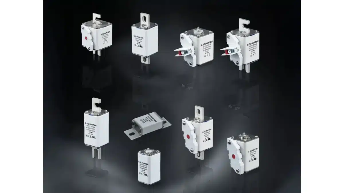
The EKO series is structured into several sub‑families with defined current ranges, voltage ratings and mounting variants. According to the manufacturer information, the key product variants are:
- EKO11: 160–400 A, 1000 VDC / 1250 VAC, available with Flush End and DIN‑Rail mounting.
- EKO12: 125–630 A, 1000 VDC, with Flush End and US Style Bolted Tag mounting.
- EKO13: 250–800 A, 1000 VDC / 1250 VAC, with Flush End and DIN‑Rail mounting.
- EKO14: 315–1100 A, 1000 VDC / 1250 VAC, with Flush End and DIN‑Rail mounting.
- EKO81: 50–400 A, 500 VDC, Bolt‑on mounting.
Additional technical points of interest:
- All series share the square‑body construction, which simplifies mechanical design and improves thermal spreading compared to smaller cylindrical fuses in high‑current applications.
- The ceramic tube provides good arc‑quenching and insulation performance at high voltages, which is critical for 1000 VDC and above.
- Tin‑plated copper alloy terminals provide low contact resistance and facilitate reliable bolted or clamp connections, which is important for minimizing I²R losses and heating at high currents.
- Optional mechanical indicators and microswitches (available for EKO11–EKO14) allow remote fuse status monitoring, which is valuable for systems deployed in unmanned stations or large cabinets.
For precise time‑current characteristics, I²t values, power dissipation and permissible pre‑arcing energy, designers should consult the official EKO series datasheet, as those values are application‑critical and not fully detailed in the press summary.
Design‑in notes for engineers
For successful design‑in of EKO HV fuses, several practical considerations should be taken into account in addition to the basic current and voltage ratings.
Key selection and design points:
- Select the voltage rating with appropriate margin versus the maximum continuous system voltage; for DC systems near 1000 V, only variants explicitly rated at 1000 VDC should be used.
- Size the fuse current rating based on the expected continuous current, ambient temperature, cooling conditions and permissible temperature rise, not just the nominal system current. Derating according to the datasheet curves is essential.
- Use the time‑current and I²t characteristics to ensure the fuse will clear worst‑case short‑circuits fast enough while not opening during inrush or temporary overloads (e.g. capacitor charging, motor starts).
- Consider the high DC breaking capacity (up to 50 kA) when calculating prospective fault currents from batteries, DC buses and upstream transformers. Ensure the EKO variant selected is coordinated with other protection devices such as contactors and circuit breakers.
- When using DIN‑Rail or Flush End mounting, verify creepage and clearance distances on the panel or busbar to maintain system insulation coordination at 1000 VDC or 1250 VAC.
- For US Style Bolted Tag and Bolt‑on versions, design sufficiently wide copper busbars or cables, with torque‑controlled bolted connections, to keep contact resistance low and avoid local hotspots.
- In applications with limited access, optional indicators and microswitches can significantly reduce troubleshooting time by allowing visual or remote sensing of fuse status; this should be considered early in the system architecture.
From a layout point of view, the square‑body form factor and broad current range can help standardize the mechanical footprint across different system power classes. However, thermal design—airflow, spacing to other components and possible use of heat‑conductive mounting surfaces—remains critical for fuses operated toward the upper end of their current and temperature ranges. Exact dimensional details and mounting recommendations should be taken from the official EKO datasheet.
Typical system use cases
In real power electronics designs, EKO fuses can occupy several roles, depending on system topology:
- DC bus protection between battery packs and inverter in EV chargers or BESS systems, limiting the energy delivered into a short‑circuit and protecting cables, busbars and semiconductor devices.
- Protection of DC link capacitor banks in UPS and drives, where fuses must clear faults inside capacitor banks or power modules without propagating damage upstream.
- Branch or feeder protection in multi‑string BESS or PV‑coupled storage systems, where each string or module may need its own HV fuse.
- Input or output protection of power conversion modules in modular UPS or multi‑inverter racks, enabling selective coordination between module‑level and system‑level protection.
In all these cases, careful coordination with system insulation, clearances and standards (e.g. IEC and UL system standards) is required. The EKO series’ compliance with multiple fuse standards and environmental directives helps simplify this aspect at component level.
Source
This article is based on Schurter’s official EKO HV fuse product communication and related publicly available information from the manufacturer. For detailed electrical characteristics, mechanical drawings and safety instructions, designers should always refer to the current manufacturer datasheet and catalog entries for the EKO series.


