Passive Components Blog
No Result
View All Result
  • Home
  • NewsFilter
    • All
    • Aerospace & Defence
    • Antenna
    • Applications
    • Automotive
    • Capacitors
    • Circuit Protection Devices
    • electro-mechanical news
    • Filters
    • Fuses
    • Inductors
    • Industrial
    • Integrated Passives
    • inter-connect news
    • Market & Supply Chain
    • Market Insights
    • Medical
    • Modelling and Simulation
    • New Materials & Supply
    • New Technologies
    • Non-linear Passives
    • Oscillators
    • Passive Sensors News
    • Resistors
    • RF & Microwave
    • Telecommunication
    • Weekly Digest

    Coupled Inductors in SEPIC versus Flyback Converters

    Vishay Releases High Current 3.3 V to 36 V ESD Protection Diodes

    TDK Extends SMT Gate Drive Transformers to 1000 V

    Non-Linear MLCC Class II Capacitor Measurements Challenges

    Researchers Demonstrated HfO Anti-Ferroelectric Flexible Capacitors

    Connector Industry Achieves Double-Digit Growth

    Stackpole Unveils Metal Element High Current Chip Jumpers

    Common Mistakes in Flyback Transformer Specs

    Vishay Releases Miniature SMD Trimmers for Harsh Environments

    Trending Tags

    • Ripple Current
    • RF
    • Leakage Current
    • Tantalum vs Ceramic
    • Snubber
    • Low ESR
    • Feedthrough
    • Derating
    • Dielectric Constant
    • New Products
    • Market Reports
  • VideoFilter
    • All
    • Antenna videos
    • Capacitor videos
    • Circuit Protection Video
    • Filter videos
    • Fuse videos
    • Inductor videos
    • Inter-Connect Video
    • Non-linear passives videos
    • Oscillator videos
    • Passive sensors videos
    • Resistor videos

    Coupled Inductors in SEPIC versus Flyback Converters

    Non-Linear MLCC Class II Capacitor Measurements Challenges

    Percolation Phenomenon and Reliability of Molded Power Inductors in DC/DC converters

    Root Causes and Effects of DC Bias and AC in Ceramic Capacitors

    How to Calculate the Output Capacitor for a Switching Power Supply

    Switched Capacitor Converter Explained

    Understanding Inductor Dot Markings and Their Application in LTspice

    Accelerating Full Bridge LLC Resonant Converter Design with Frenetic AI

    Understanding Switched Capacitor Converters

    Trending Tags

    • Capacitors explained
    • Inductors explained
    • Resistors explained
    • Filters explained
    • Application Video Guidelines
    • EMC
    • New Products
    • Ripple Current
    • Simulation
    • Tantalum vs Ceramic
  • Knowledge Blog
  • Suppliers
    • Who is Who
  • Events
No Result
View All Result
Passive Components Blog
No Result
View All Result

AEM Compares Auto-Grade Surface-Mount Wire-in-Air Fuse Performance Under Extreme Electric Vehicle Conditions

24.9.2017
Reading Time: 2 mins read
A A

source: AEM Components news

Novi, Mich.—September 12, 2017 — EETech Labs, in cooperation with AEM Components, has produced a video that demonstrates the effect on circuit protection devices when subjected to worst case electric vehicle (EV) battery short circuit conditions. This comparison study highlights the advantages of using AEM (AirMatrix®) wire-in-air fuse versus similarly rated competitive surface mount fuses.

RelatedPosts

Coupled Inductors in SEPIC versus Flyback Converters

Vishay Releases High Current 3.3 V to 36 V ESD Protection Diodes

TDK Extends SMT Gate Drive Transformers to 1000 V

The video clearly displays the adverse effects that short circuits from EV batteries can exert on a fuse. Automotive specifications require circuit protection to break the circuit without causing damage to PC boards or other components in the system. The AEM wire-in-air fuse technology is able to comply with this prerequisite by remaining intact. Competitive fuses that were also tested under the same conditions not only caught on fire, they also caused damage to the PCB on which they were mounted.

AEM AirMatrix® fuses are designed to meet stringent automotive standards, so testing for worst case conditions is critical. When testing in electric and plug-in hybrid vehicles battery systems, a short circuit condition is created for all batteries in the array, causing the full amount of current to be present at the fuse. Assuring that the fuse opens properly and protects the battery system is of primary concern.

“The fusible element in the QA Series wire-in-air devices is uniformly straight across the internal cavity and externally bonded to the endcap through the plating process,” reports Jeffers Liu, AEM Components’ Vice President of Sales and Marketing. “Competitive units utilize solder joints inside a ceramic tube to secure the fusible link. This traditional approach has the drawback of non-uniform performance and potential internal connection failure caused by mechanical/thermal stress like vibration or bending, or by common soldering defects like cold joints or poor wetting. As the YouTube video demonstrates, under high-stress conditions, the solder can vaporize, causing prolonged arcing that can lead to package failure and damage to the circuit board and surrounding components. In comparison, our automotive-grade fuses stand up under the same stress since they are designed specifically to enhance reliability in harsh environments by eliminating the solder joint.”

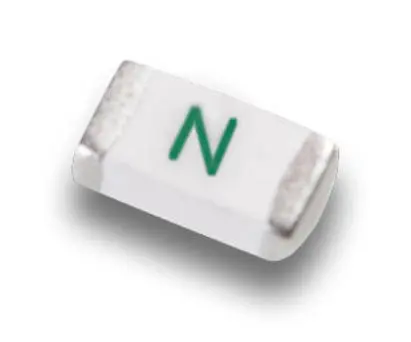
The new wire-in-air AirMatrix (QA-F Series and QA-H Series) are manufactured in AEM’s TS16949-certified facility. The QA Series features the industry’s highest current ratings – up to 20A/250V and its proprietary, air-tight, wire-in-air structure assures consistent electrical performance. The QA Series is offered in two fast-acting versions: a 2410 package (QA-F Series) with a 0.5-20A/65-250V rating and a 1206 (QA-H Series) package rated at 1.5-15A/32-65V.

Pricing and Availability
The QA Series is now available in mass quantities. Prices range from $0.065 to $0.20 per unit for OEM quantities. For samples, interested parties can contact a local AEM Distributor.


Related

Recent Posts

Vishay Releases High Current 3.3 V to 36 V ESD Protection Diodes

25.8.2025
4

Littelfuse Unveils High-Precision TMR Angle Magnetic Sensors

13.8.2025
12

Stackpole Extends Voltage of High Temp Chip Resistors

13.8.2025
11

High Voltage MLCCs Meeting the Growing Demand for Efficiency in Power Conversion

12.8.2025
148

TDK Releases Compact Polypropylene Film Capacitors for Resonant Topologies

7.8.2025
35

Knowles Unveils High-Performance Safety-Certified MLCC Capacitors

6.8.2025
48

Vishay Releases High Saturation 180C Automotive Inductors

6.8.2025
27

SCHURTER Releases Chip Fuse for ATEX and Precision Applications

4.8.2025
18

Hirose Releases High Current Vibration-Resistant Connectors

4.8.2025
11

PCNS 2025 Final Program Announced!

4.8.2025
98

Upcoming Events

Aug 27
17:00 - 18:00 CEST

Capacitor Assemblies for High-Power Circuit Designs

Sep 3
15:30 - 17:30 CEST

How to Choose Your Magnetic Supplier

Sep 16
17:00 - 18:00 CEST

EMI Shielding Challenges

Sep 22
September 22 @ 13:00 - September 25 @ 15:15 EDT

Pre Cap Visual Inspection per Mil-Std-883 (TM 2017)

Sep 30
September 30 @ 12:00 - October 2 @ 14:00 EDT

MIL-Std-883 TM 2010

View Calendar

Popular Posts

  • Buck Converter Design and Calculation

    0 shares
    Share 0 Tweet 0
  • Boost Converter Design and Calculation

    0 shares
    Share 0 Tweet 0
  • Flyback Converter Design and Calculation

    0 shares
    Share 0 Tweet 0
  • LLC Resonant Converter Design and Calculation

    0 shares
    Share 0 Tweet 0
  • What is a Dielectric Constant and DF of Plastic Materials?

    4 shares
    Share 4 Tweet 0
  • Ripple Current and its Effects on the Performance of Capacitors

    3 shares
    Share 3 Tweet 0
  • Dual Active Bridge (DAB) Topology Explained

    0 shares
    Share 0 Tweet 0
  • How to Design an Inductor

    0 shares
    Share 0 Tweet 0
  • Core Materials, Permeability and Their Losses

    0 shares
    Share 0 Tweet 0
  • MLCC Case Sizes Standards Explained

    0 shares
    Share 0 Tweet 0

Newsletter Subscription


Passive Components Blog

© EPCI - Leading Passive Components Educational and Information Site

  • Home
  • Privacy Policy
  • EPCI Membership & Advertisement
  • About

No Result
View All Result
  • Home
  • Knowledge Blog
  • Premium Suppliers

© EPCI - Leading Passive Components Educational and Information Site

This website uses cookies. By continuing to use this website you are giving consent to cookies being used. Visit our Privacy and Cookie Policy.
Go to mobile version