


Capacitors are used in both analog and digital circuits to remove unwanted signals. The filtering performance of a capacitor or filtering circuit is commonly described in terms of insertion loss. Some of the factors that significantly affect the insertion loss performance of a filtering circuit include configuration of the filtering elements, impedance, and load current.
Key Takeaways
- Capacitors are essential for EMI filtering in circuits and their performance is measured by insertion loss.
- Insertion loss characteristics depend on various factors including component configuration and parasitic inductance.
- Three-terminal and feed-through capacitors improve insertion loss at high frequencies compared to standard two-terminal capacitors.
- Optimal filtering performance often requires multi-element configurations like L-C, Pi, and T.
- Careful PCB layout and element selection are crucial to meet noise reduction targets in demanding applications.
Filtering EMI in Circuits
Electrical disturbances, both natural and man-made, can significantly affect the performance of an electronic circuit. These unwanted signals are collectively known as electromagnetic interference (EMI). Filtering circuits are used in most analog and digital circuits to eliminate these unwanted signals. Some of the most common sources of these signals include lighting, storms, precipitation, power lines, motors, ignition systems, radar transmitters, power amplifiers, computer clocks and cosmic sources.
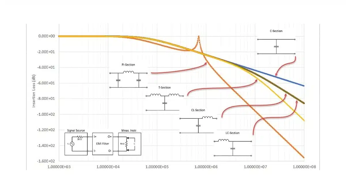
The configuration of elements in a filtering circuit significantly determines its filtering performance. The simplest filtering configuration, commonly known as C filter, consists of a single feed-through capacitor. The performance of a filtering circuit is improved by using a combination of capacitive and inductive elements. Some of the most common configurations include L-C, T, and Pi constructions. Increasing the number of capacitive and inductive elements helps to improve the performance of a filtering circuit.
Insertion loss characteristics of capacitors and circuits
One of the key factors to consider when selecting a capacitor for EMI filtering is its insertion loss characteristics. Insertion loss describes how much a filter attenuates a signal between source and load, typically in a standardized system such as 50 Ω / 50 Ω. In voltage form it is defined as
,
while in power form
In practice, insertion loss is almost always specified in decibels over frequency.
In a basic test circuit, these voltages or powers are measured at the same load point before and after inserting the filtering component. This parameter directly determines the level of attenuation that the filtering circuit can provide.
Insertion loss curves in capacitor and filter datasheets are usually measured in a 50 Ω source / 50 Ω load configuration using a network analyzer. When comparing components, it is therefore important to check that the test impedance and configuration are the same, otherwise the apparent performance differences may only come from the measurement setup.
Ordinary capacitors do not have good insertion loss performance characteristics. The presence of inherent parasitic ESL self-inductance reduces their ability to ground unwanted electrical disturbances. This residual inductance increases with an increase in the length of electrodes.
In addition, the narrower the electrode is, the higher the amount of inductance. To reduce this unwanted inductance and improve the filtering performance of capacitors, it is necessary to modify the architecture of these passive components. Changing the architecture of a capacitor and adding a third terminal helps to minimize residual inductance. Feed-through capacitors, a special class of capacitive elements that are widely used for filtering applications, are based on this modified architecture.
In capacitors with two terminals, the residual inductance is higher because the leads of a component behave as inductors. Introducing a third terminal helps to reduce the inductance component in series with the capacitive component. This significantly improves the insertion loss characteristics of a capacitor. By reducing this residual inductance, the self-resonance frequency of a filtering capacitor is increased. In terms of insertion loss curves, this architecture shift typically translates into significantly higher attenuation above a few MHz compared to an otherwise similar 2‑terminal MLCC. In many EMI filters, replacing a 2‑terminal capacitor with a suitable feed‑through part allows designers to reduce the number of additional stages needed to meet a given attenuation target.
Feed-through capacitors are specially designed to provide exceptional insertion loss performance. These capacitors are widely used for EMI suppression and bypassing applications. The most common designs of ceramic feed-through capacitors used in today’s filtering circuits are discoidal and tubular capacitors. Plastic film feed-through capacitors are commonly used in applications that demand high reliability.
Insertion loss variation with frequency
The insertion loss characteristics of ideal and actual capacitors are slightly different. The insertion loss of an ideal capacitor increases with an increase in frequency. In comparison, the insertion loss of an actual component increases with frequency up to a certain level. This level is known as self-resonance frequency. After this level, the insertion loss of an actual component decreases with an increase in frequency.
For example, an ideal 1 nF capacitor used as a shunt element in a 50 Ω system would show a monotonically increasing insertion loss with frequency, because its reactance keeps falling. A real 1 nF capacitor will instead reach a maximum insertion loss at its self‑resonant frequency (where the capacitive reactance and parasitic series inductance cancel) and then gradually lose effectiveness at higher frequencies as it behaves more inductive than capacitive.
At frequencies higher than the resonance frequency, the insertion loss performance of a filter does not change if the residual inductance is maintained constant. Increasing or decreasing the capacitance of a component under these conditions does not affect the insertion loss. This means that a capacitor with a high self-resonance frequency is required for noise suppression at high frequencies. Components with small residual inductances should be used for such applications.
Factors that determine insertion loss performance
The insertion loss performance of a circuit or a component is determined by many factors; some of the main factors are electrical configuration, load current, source impedance, load impedance, earthing impedance, characteristics of the dielectric materials of components, and shielding integrity.
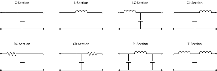
Configuration of components
Although single elements can be used to remove unwanted signals, most filtering circuits use a combination of capacitive and inductive components. The choice of configuration is mostly determined by the desired insertion loss performance. The most common configurations include C, C-L, L-C, Pi and T. See figure below:
| Configuration | Elements | Typical slope (per decade) | Typical use case |
|---|---|---|---|
| C | 1 C | ~20 dB/decade | Simple decoupling, low‑cost EMI reduction |
| L‑C or C‑L | 1 L, 1 C | ~40 dB/decade | Better line filtering, DC supply input filters |
| Pi | 2 C, 1 L | ~60 dB/decade | High attenuation near a single cutoff, line filters |
| T | 1 C, 2 L | ~60 dB/decade | Higher source/load isolation, more complex EMI situations |
Advanced: simple insertion loss estimation
As a rough check, a single‑pole low‑pass with cutoff frequency provides about 20 dB of additional attenuation at 10 × and 40 dB at 100 × , assuming matched impedances. A 2‑pole filter adds another 20 dB per decade. This rule of thumb is useful when selecting the number of stages required to meet a given EMI limit before you move to full simulation or measurement.
Theoretically speaking, a single element filter yields an insertion loss of 20 dB per decade while a two-element filter yields 40 dB per decade. Filtering circuits with three or more elements can yield even better insertion loss performance.
Filtering circuits with multiple capacitive and inductive elements are used in circuits where high degrees of filtering performance are required. The actual insertion loss performance is determined by the actual characteristics of components used. This information is usually provided in data sheets. It is important to consider your source and load impedances when selecting a configuration for your filtering circuit.
In real designs, parasitic inductances and capacitances of the PCB layout can significantly modify the expected theoretical insertion loss. Short, wide traces and a low‑inductance ground connection are essential if you want the filter to reach its calculated attenuation at high frequency.
Load current
The effect of load current on insertion loss is significantly determined by the properties of the filtering elements used. For filtering circuits with inductive elements, the insertion loss can drop if ferrite inductors are used. The degree of this effect depends on the specific characteristics of the ferrite material.
At high DC load currents, the core of a ferrite inductor may approach saturation, which reduces its incremental inductance and therefore decreases the effective insertion loss at the affected frequencies. Checking the inductor’s DC bias curves is therefore as important as checking the capacitor’s voltage‑dependent behavior.
Circuit impedances
The insertion loss performance of a filtering circuit is greatly dependent on source and load impedances. This performance is usually optimized by choosing a suitable configuration of capacitive and inductive elements.
A filter designed and specified for 50 Ω terminations can behave very differently when connected between a low‑impedance power stage and a high‑impedance load. Matching the filter topology to realistic source and load impedances in your application is often more important than simply increasing the nominal capacitance or inductance.
Conclusion
Capacitors are key elements of EMI filters in both analog and digital circuits, and their effectiveness is best described by insertion loss over frequency. Insertion loss depends not only on the nominal capacitance but also on parasitic inductance, electrical configuration, load current, and the real source and load impedances in the application.
Three‑terminal and feed‑through capacitors reduce residual inductance and can deliver much higher insertion loss at high frequencies than conventional 2‑terminal parts. In demanding EMI environments, multi‑element filters (L‑C, Pi, T) combined with careful PCB layout are typically required to meet regulatory and functional noise limits.
FAQ about Insertion Loss and Filter Capacitors
Insertion loss is a measure of how much a filter attenuates a signal between source and load, usually expressed in decibels over frequency. It compares the voltage or power at the load with and without the filter in place and is typically specified using standardized test conditions such as a 50 Ω source and 50 Ω load.
Capacitors are used as shunt elements that divert high-frequency noise to ground and therefore help remove unwanted EMI signals from analog and digital circuits. When combined with inductors in low-pass filter topologies such as C, L-C, Pi, or T filters, they increase insertion loss and improve overall noise suppression.
Three-terminal and feedthrough capacitors have a modified internal architecture that reduces residual series inductance in the current path. Lower inductance raises the self-resonant frequency and provides significantly higher insertion loss at high frequencies compared with conventional two-terminal capacitors, which improves EMI filtering performance.
For an ideal capacitor, insertion loss increases continuously with frequency because its reactance decreases. A real capacitor reaches a maximum insertion loss at its self-resonant frequency, where capacitance and parasitic inductance cancel, and then loses effectiveness at higher frequencies as it behaves more like an inductor.
Key factors include the electrical configuration of capacitors and inductors, the source and load impedances, the DC load current, the dielectric material properties, the earthing impedance, and the quality of shielding. PCB layout parasitics, such as trace inductance and ground connection quality, also strongly influence the real insertion loss achieved in a circuit.
Multi-element filters such as L-C, Pi, or T configurations are preferred when high insertion loss is required across a broad frequency range or when EMI regulations are strict. They combine multiple capacitive and inductive elements to achieve steeper attenuation slopes than a single C filter, which is typically used only for simple decoupling or low-cost EMI reduction.
How to Select Filter Capacitors for Optimal Insertion Loss
- Step 1: Define the noise problem and frequency range
dentify the main EMI sources in your application, such as switching converters, motors, clocks, or external interference, and determine the frequency range that must be attenuated. This gives you a target band where the filter must provide sufficient insertion loss.
- Step 2: Determine source and load impedances
Estimate or measure the realistic source and load impedances seen by the filter instead of assuming ideal 50 Ω terminations. Use these impedances as the basis for choosing a suitable low-pass filter topology and for interpreting datasheet insertion loss curves.
- Step 3: Choose the filter configuration
Select a filter topology that matches your attenuation target: use a simple C filter for basic decoupling, an L-C or C-L filter for stronger line filtering, and Pi or T filters when you need higher insertion loss and steeper attenuation slopes. Remember that each additional reactive element adds roughly 20 dB of attenuation per decade in the ideal case.
- Step 4: Select capacitor technology and value
Pick capacitor types and values that provide low impedance and high self-resonant frequency in the noise band of interest. For demanding EMI suppression above a few megahertz, consider three-terminal or feedthrough capacitors, which reduce residual inductance and improve high-frequency insertion loss compared with standard two-terminal MLCCs.
- Step 5: Consider inductors, load current, and core characteristics
If your filter uses inductors, choose parts with suitable inductance, current rating, and ferrite material so that they do not saturate at the expected DC load current. Saturation reduces effective inductance and degrades insertion loss in the affected frequency range.
- Step 6: Optimize PCB layout and grounding
Implement the filter with short, wide traces and low-inductance connections to ground to minimize parasitic inductances. Place feedthrough and decoupling capacitors close to the noise source or interface and ensure that the ground return path is compact to preserve the theoretical insertion loss.
- Step 7: Verify insertion loss against requirements
Compare your design targets with datasheet insertion loss curves measured under 50 Ω conditions, then validate performance in your real circuit using network analyzer or EMI measurements. Adjust component values, topology, or capacitor technology as needed if the measured insertion loss does not meet your EMI limits.
Further Reading on Insertion Loss and Filters
For readers who want to explore specific aspects of insertion loss and filter capacitor performance in more detail, see the following Knowledge Blog articles:
- Feedthrough Capacitors Technology and Applications – Technology overview of feedthrough capacitors, their geometry, and why they offer outstanding insertion loss at high frequencies compared with conventional 2‑terminal capacitors.
- AC Line Filters and Insertion Loss Explained – A deeper look at insertion loss measurement for complete AC line filters, typical test setups, and how capacitor choice affects overall filter performance.
- How Passive Low Pass Filters Work – Fundamentals of passive low‑pass filters (L, Pi, T), cut‑off frequency, and attenuation slope, providing the theoretical background for the filter configurations mentioned in this article.
- Insertion Loss and Performance in EMI Filtering – Detailed discussion of the main factors that determine insertion loss performance: electrical configuration, source/load impedances, load current, dielectric material, and shielding.


