


The article explains capacitor derating principle and introduce category concepts.
Key Takeaways
- Capacitors derating involves using capacitors at lower than rated voltage, usually determined by voltage and temperature rules.
- Key parameters include voltage and temperature derating, both of which affect reliability and operational performance.
- Derating guidelines vary by capacitor type; for example, tantalum capacitors have specific surge current load limitations.
- Reduced voltage improves reliability and extends the lifecycle of capacitors, especially aluminum electrolytic types.
- Understanding derating requirements is essential for proper application and component selection in circuit design.
Almost all major capacitor technologies need a certain derating at their corner operating conditions. However, physical reasons for this may be specific to individual capacitor technology – reliability, stability of the main electrical parameters or protection against excessive surge current …
There are two most common derating parameters: voltage (that may include hidden current limitation) and temperature
The derating factors are typically in “OR“, “whatever is greater” logic relationship, so if the voltage derating rule says 20% and due to the temperature you have to derate 30% as well, “whatever is greater” condition applies – it means that the 30% derating is covering both voltage and temperature derating requirements.
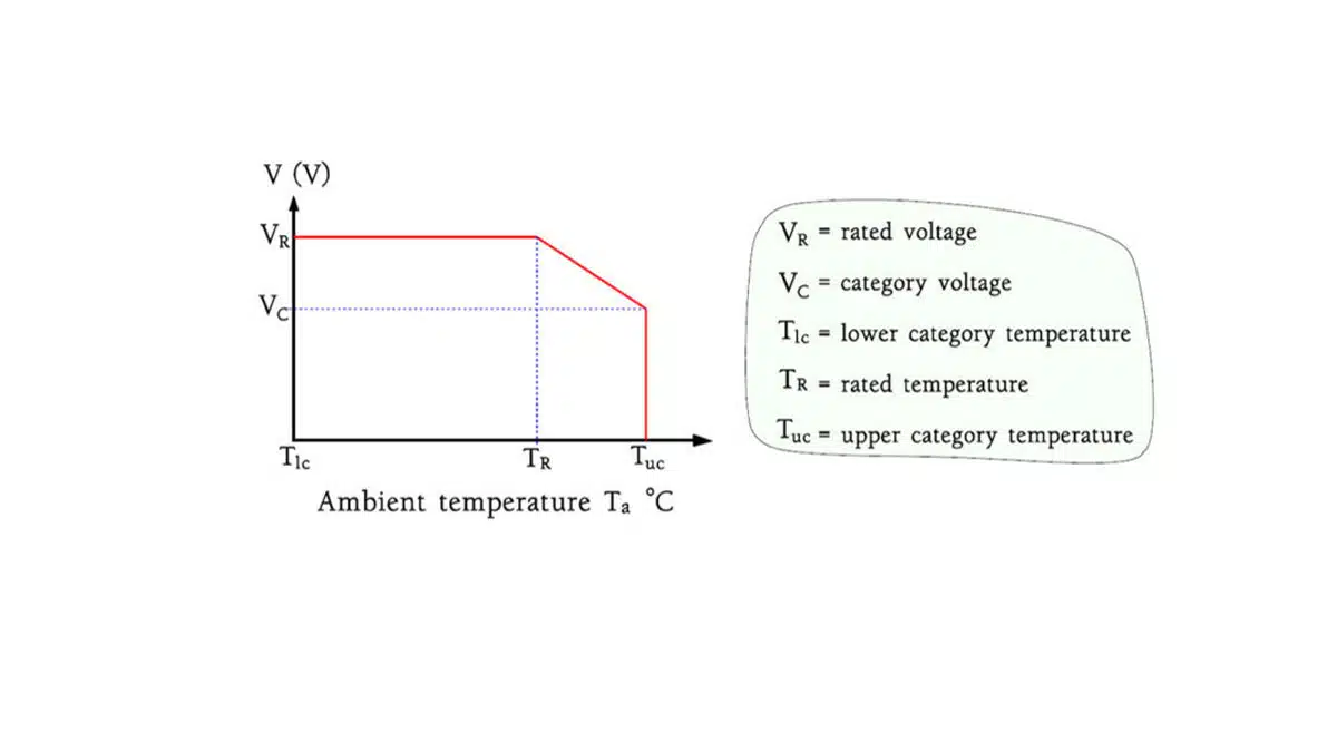
Example of capacitor voltage – derating chart:
Category Concepts and Derating
Recommendation for voltage derating means that the actual capacitor shall be used in the application at lower voltage than rated voltage. Derating is expressed usually by percentage of rated voltage that shall be subtracted. For example 20% derating means that the capacitor shall be used at 80% of rated voltage at the specific applications (10V capacitor to be used on 8V maximum).
The purpose of the derating is to reduce amount of load accelerating factors to the capacitors. The two main accelerating factors are voltage and temperature.
As per the equation C1-20 energy content is depending to voltage squared, thus voltage reduction (voltage derating) has a significant impact to overall energy handling through the capacitor. Reasons for voltage derating can be various depending to the capacitor technology, construction and applications. The main general reasons for voltage derating can be as follows, nevertheless it may be good to study the capacitor manufacturer’s application guidelines.
- high operating temperature derating (“temperature derating”) and category concepts
Capacitors designed for DC voltages produce no internal heating. Therefore they often can be used with more or less reduced voltages up to the so called upper category voltage where the temperature characteristics of the material put a limit. This occur at the upper category temperature, TUC, in other nomenclatures called maximum usage temperature. The connections are shown in the following Figure 2. Varying derating curves are shown in MIL-HDBK-1547.
Note: derating due to the high operating temperature (see below) is sometimes called “temperature derating”, but this may cause some confusion. Degradation mechanisms are usually accelerated by both temperature and voltage factors, just with different root coefficient and predominant impacts. Thus the term “temperature derating” should be left to “limitation of use of the capacitor at lower then rated temperature due to a predominant temperature driven physical degradation mechanism”. In other words, we need mostly to have a voltage derating in place to limit amount of overall energy in the capacitor, but in some cases degradation process is accelerated more by temperature factor (and we want to limit this by limitation of maximum exposed temperature “temperature derating”)
- surge current load limitation
Some capacitors, such as tantalum solid capacitors, may have limitation in its maximum allowed current surge spike. Current surge overloading may cause in some cases even thermal destruction and fatal failures in some cases. The practical method to increase the surge current load capability is to use higher voltage capacitor, in other words use higher voltage derating. The derating recommendation may be then dependent to circuit function, application or specific capacitor technology.
As an example of solid tantalum capacitors the basic rules are:
tantalum MnO2 capacitors: 50% derating in high current surge applications (such as input side of DC/DC converters or directly on battery), 20% for other applications (coupling, timing, DC/DC output)
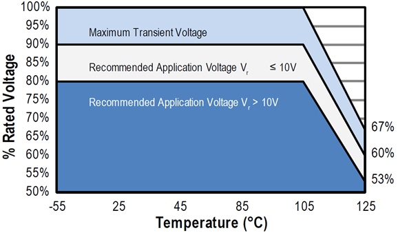
tantalum polymer capacitors: 10% for all circuits for <= 10V capacitors, 20% for all circuits for >10V capacitors
These derating guidelines are typically specified to 105°C (temperature derating). Additional derating may be necessary up to 125°C.
- reliability improvement
voltage is one of the strongest accelerator for number of failure mechanisms and thus its reduction may significantly improve the component reliability.
As an example aluminium electrolytic or film capacitors life time is strongly influenced by applied voltage and voltage derating is the most effective way to increase life time and reduce MTBF rate.
- capacitors electrical parameters stability (MLCC capacitors)
voltage may play an important inhibitor role in number of mechanisms. High K ferro-dielectrics such as BaTiO3 used in Class II MLCC capacitors are featuring strong dependency of capacitance value to AC and DC voltage (DC BIAS voltage impact). Applied voltage is also condition for piezo-effect that may cause harmful audio noise generation by MLCC class II capacitors.
Voltage derating may significantly suppress these phenomenons and thus improve performance of MLCC class II capacitors.
Multiplication of derating requirements
Different voltage derating requirements are usually in “OR” logic,”whatever is greater” relation. It means that the greatest derating principle is applied only.
in example: 12V input side of DC/DC converter (high surge current load application). Maximum operated temperature of end devices: 125°C and 105°C. Can we use 16V tantalum polymer or tantalum MnO2 capacitors?
- 125°C device with tantalum polymers: 20% voltage derating is recommended for 16V tantalum polymer capacitor in all applications and there is also 33% derating needed at 125°C (no derating to 105°C). You can apply maximum 10.7V to the capacitor for the entire operation temperature range to 125°C (voltage derating 20% is covered by the 33% temperature derating). Thus 16V capacitor is NOT suitable for 125°C device due to the high temperature. Need higher rated 20V tantalum polymer capacitor.
- 105°C device with tantalum polymers: there is no derating due to the temperature at 105°C, thus 20% derating for all circuits would apply only. It means 16V tantalum polymer capacitors CAN BE USED used up to 12.8V in the 105°C entire temperature range.
- Can tantalum MnO2 capacitors be used ? Tantalum MnO2 capacitors require 50% derating for hard surge current applications, thus 25V capacitors has to be used in this application. There is also 33% derating for 125°C device, but this is not effective as the 33% derating due to temperature is covered by the 50% derating due to the surge current limitation. 16V tantalum MnO2 capacitors can be used at other non-surge critical circuit applications (output of the DC/DC, timing, coupling …) reflecting the 20% derating rule due to the surge and the same derating due to the temperature as tantalum polymer capacitors.
FAQ: Capacitor Derating and Category Concepts
Capacitor derating is the practice of using a capacitor at a lower voltage or temperature than its rated maximum. This reduces stress, improves reliability, and extends component lifetime.
Voltage derating lowers the applied voltage to reduce energy stress, suppress degradation mechanisms, and improve stability of electrical parameters, especially in MLCCs and tantalum capacitors.
Derating reduces stress factors such as voltage, temperature, and surge current. This minimizes failure mechanisms, extends capacitor lifetime, and improves MTBF (Mean Time Between Failures).
Derating reduces stress factors such as voltage, temperature, and surge current. This minimizes failure mechanisms, extends capacitor lifetime, and improves MTBF (Mean Time Between Failures).
How-to: Apply Capacitor Derating in Design
- Identify capacitor type and rating
Check the capacitor’s rated voltage, temperature, and technology (MLCC, tantalum, electrolytic, film, etc.).
- Apply voltage derating
Reduce the applied voltage by the recommended percentage. For example, use 80% of rated voltage for general applications or 50% for high surge MnO₂ tantalum capacitors.
- Consider temperature derating
At high operating temperatures (e.g., 125°C for example), apply additional derating as specified by manufacturer guidelines.
- Account for surge current limitations
Depending to the capacitor technology – for circuits with high inrush or surge currents, select capacitors with higher voltage ratings or apply stricter derating rules.
- Verify reliability and compliance
Ensure the chosen derating strategy aligns with application requirements, improves reliability, and complies with manufacturer recommendations.


