Passive Components Blog
No Result
View All Result
  • Home
  • NewsFilter
    • All
    • Aerospace & Defence
    • Antenna
    • Applications
    • Automotive
    • Capacitors
    • Circuit Protection Devices
    • electro-mechanical news
    • Filters
    • Fuses
    • Inductors
    • Industrial
    • Integrated Passives
    • inter-connect news
    • Market & Supply Chain
    • Market Insights
    • Medical
    • Modelling and Simulation
    • New Materials & Supply
    • New Technologies
    • Non-linear Passives
    • Oscillators
    • Passive Sensors News
    • Resistors
    • RF & Microwave
    • Telecommunication
    • Weekly Digest

    Würth Elektronik Unveils Compact Common-Mode Data Lines Chokes

    Bourns Releases TCO 240 Watt USB Mini-Breaker

    Littelfuse Adds 600W Automotive TVS Diodes for High-Energy Transient Protection

    Vishay Releases Harsh Environment Robust DC-Link Film Capacitor

    Bourns Releases Automotive High Creepage and Clearance Transformer

    Bourns Unveils Metal Powder Core High Current Low DCR Shielded Power Inductor

    Influence of Tantalum Capacitor Pellets Size on Stability During Oxide Film Formation

    Modelithics Release Discrete Components Optimization Article for RF/Microwave Designers

    Samsung Extends Capacitance of MLCC 0805 X7T 250V to 100nF

    Trending Tags

    • Ripple Current
    • RF
    • Leakage Current
    • Tantalum vs Ceramic
    • Snubber
    • Low ESR
    • Feedthrough
    • Derating
    • Dielectric Constant
    • New Products
    • Market Reports
  • VideoFilter
    • All
    • Antenna videos
    • Capacitor videos
    • Circuit Protection Video
    • Filter videos
    • Fuse videos
    • Inductor videos
    • Inter-Connect Video
    • Non-linear passives videos
    • Oscillator videos
    • Passive sensors videos
    • Resistor videos

    Ripple Steering in Coupled Inductors: SEPIC Case

    SEPIC Converter with Coupled and Uncoupled Inductors

    Coupled Inductors in SEPIC versus Flyback Converters

    Non-Linear MLCC Class II Capacitor Measurements Challenges

    Percolation Phenomenon and Reliability of Molded Power Inductors in DC/DC converters

    Root Causes and Effects of DC Bias and AC in Ceramic Capacitors

    How to Calculate the Output Capacitor for a Switching Power Supply

    Switched Capacitor Converter Explained

    Understanding Inductor Dot Markings and Their Application in LTspice

    Trending Tags

    • Capacitors explained
    • Inductors explained
    • Resistors explained
    • Filters explained
    • Application Video Guidelines
    • EMC
    • New Products
    • Ripple Current
    • Simulation
    • Tantalum vs Ceramic
  • Knowledge Blog
  • Suppliers
    • Who is Who
  • Events
No Result
View All Result
Passive Components Blog
No Result
View All Result

Choosing High-Frequency Capacitors; Role of Dielectric Material

12.7.2024
Reading Time: 3 mins read
A A

This article based on Knowles Precision Devices blog explains role of dielectric material when choosing high-frequency capacitors.

Radio frequency (RF) and microwave applications involve the transmission and receipt of high-frequency electromagnetic signals. RF refers to alternating current (AC) signals at 3 kHz to 300 GHz, and microwave refers to a higher range, closer to 300 MHz to 300 GHz. 

RelatedPosts

Knowles Unveils High-Performance Safety-Certified MLCC Capacitors

Knowles Releases Inductors for Mission-Critical RF Applications

Learn How Supercapacitors Enhance Power System in Knowles eBook

Capacitance, and by extension impedance, varies with frequency, so capacitors play a variety of critical roles in these RF and microwave circuits. With many options for configuration, they function in energy storage and voltage regulation, DC blocking, impedance matching, filtering and more. 

When choosing high-frequency ceramic capacitors for radio frequency (RF) and microwave applications, several factors come into play. Let’s explore some key considerations:

  1. Dielectric Material:
    • The type of dielectric material significantly impacts the capacitance achievable in a given area.
    • For AC coupling/DC blocking applications with more forgiving requirements, consider Class II dielectrics.
    • For tighter tolerances, such as LC filters, Class I dielectrics are preferable due to their excellent stability and low-loss characteristics.
  2. Additional Factors:
    • Low Loss Tangent: Opt for materials with a low loss tangent to reduce dielectric loss.
    • Uniform, Isotropic Dielectric Constant: Minimize inconsistencies like impedance changes within the circuit.
    • Batch-to-Batch Repeatability: Ensures consistent manufacturing.
    • Smooth Surface Finish: Reduces conductor ohmic losses.
    • High Thermal Conductivity: Important for power electronics circuits.
    • Thermal Expansion: Comply with component and package requirements.

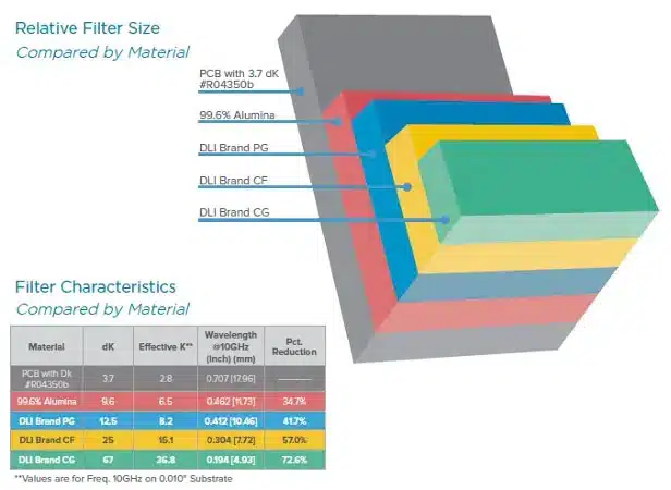
Understanding the capacitance achievable in a given area is an important factor in choosing capacitors for your application. This is ultimately determined by the type of dielectric material that can meet your application requirements for space and capacitance, see Figure 1.  

Figure 1: Comparing dielectric materials by relative filter size and characteristics 

For AC coupling/DC blocking applications where capacitance tolerance and temperature stability requirements are more forgiving, consider Class II dielectrics. In applications with tighter tolerances, like LC filters, Class I dielectrics are a better choice because of their excellent stability and low-loss characteristics.  

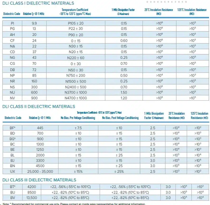
A majority of Knowles Precision Devices’ single-layer capacitors (SLCs) are 0.02” x 0.02” (20 mil sq) to 0.03” x 0.03” (30 mil sq). That said, we’ve seen growing demand to lower case sizes to 0.010” x 0.010” (10 mil sq). To meet this demand, Knowles Precision Devices has a range of offerings from a dielectric constant (K) of 9 through 45000. See Figure 2 for Knowles Precision Devices Class I and Class II dielectric materials and relevant specifications.  

Figure 2: Knowles Precision Devices Class I, II and III dielectric material offerings and key specifications to consider 

There are additional factors at play when selecting components for high-frequency, high-performance applications. Substrate properties, like surface finish, and fabrication processes, like metallization, impact the accuracy of line width and gap width. Both of these parameters impact overall circuit performance.

Related

Source: Knowles Precision Devices

Recent Posts

Vishay Releases Harsh Environment Robust DC-Link Film Capacitor

2.9.2025
8

Influence of Tantalum Capacitor Pellets Size on Stability During Oxide Film Formation

29.8.2025
26

Modelithics Release Discrete Components Optimization Article for RF/Microwave Designers

28.8.2025
13

Samsung Extends Capacitance of MLCC 0805 X7T 250V to 100nF

28.8.2025
26

Ripple Steering in Coupled Inductors: SEPIC Case

27.8.2025
19

Samsung Releases Ultra–High-Capacitance 4.7uF 2.5V MLCC in 0201 for AI GPU

27.8.2025
36

SEPIC Converter with Coupled and Uncoupled Inductors

26.8.2025
31

Coupled Inductors in SEPIC versus Flyback Converters

26.8.2025
21

Non-Linear MLCC Class II Capacitor Measurements Challenges

19.8.2025
62

Researchers Demonstrated HfO Anti-Ferroelectric Flexible Capacitors

19.8.2025
19

Upcoming Events

Sep 16
17:00 - 18:00 CEST

EMI Shielding Challenges

Sep 22
September 22 @ 13:00 - September 25 @ 15:15 EDT

Pre Cap Visual Inspection per Mil-Std-883 (TM 2017)

Sep 30
September 30 @ 12:00 - October 2 @ 14:00 EDT

MIL-Std-883 TM 2010

Oct 17
12:00 - 14:00 EDT

External Visual Inspection per MIL-STD-883 TM 2009

Oct 20
October 20 - October 23

Digital WE Days 2025 – Virtual Conference

View Calendar

Popular Posts

  • Buck Converter Design and Calculation

    0 shares
    Share 0 Tweet 0
  • Boost Converter Design and Calculation

    0 shares
    Share 0 Tweet 0
  • Flyback Converter Design and Calculation

    0 shares
    Share 0 Tweet 0
  • LLC Resonant Converter Design and Calculation

    0 shares
    Share 0 Tweet 0
  • What is a Dielectric Constant and DF of Plastic Materials?

    4 shares
    Share 4 Tweet 0
  • Ripple Current and its Effects on the Performance of Capacitors

    3 shares
    Share 3 Tweet 0
  • Dual Active Bridge (DAB) Topology Explained

    0 shares
    Share 0 Tweet 0
  • How to Design an Inductor

    0 shares
    Share 0 Tweet 0
  • Core Materials, Permeability and Their Losses

    0 shares
    Share 0 Tweet 0
  • MLCC Case Sizes Standards Explained

    0 shares
    Share 0 Tweet 0

Newsletter Subscription


Passive Components Blog

© EPCI - Leading Passive Components Educational and Information Site

  • Home
  • Privacy Policy
  • EPCI Membership & Advertisement
  • About

No Result
View All Result
  • Home
  • Knowledge Blog
  • Premium Suppliers

© EPCI - Leading Passive Components Educational and Information Site

This website uses cookies. By continuing to use this website you are giving consent to cookies being used. Visit our Privacy and Cookie Policy.
Go to mobile version