Passive Components Blog
No Result
View All Result
  • Home
  • NewsFilter
    • All
    • Aerospace & Defence
    • Antenna
    • Applications
    • Automotive
    • Capacitors
    • Circuit Protection Devices
    • electro-mechanical news
    • Filters
    • Fuses
    • Inductors
    • Industrial
    • Integrated Passives
    • inter-connect news
    • Market & Supply Chain
    • Market Insights
    • Medical
    • Modelling and Simulation
    • New Materials & Supply
    • New Technologies
    • Non-linear Passives
    • Oscillators
    • Passive Sensors News
    • Resistors
    • RF & Microwave
    • Telecommunication
    • Weekly Digest

    Bourns Releases Automotive 1W Flyback Transformer

    Wk 20 Electronics Supply Chain Digest

    Inductor Resonances and its Impact to EMI

    Developing Low Inductance Film Capacitor using Bode 100 Analyzer

    Highly Reliable Flex Rigid PCBs, Würth Elektronik Webinar

    Würth Elektronik Releases High Performance TLVR Coupled Inductors

    YAGEO Extends Rectangular Aluminum Electrolytic Capacitor Family

    Dr. Tomas Zednicek Vision for Europe 2025 Passive Electronics Market

    Littelfuse Releases Industry-First SMD Fuse with 1500A Interrupting Rating at 277V

    Trending Tags

    • Ripple Current
    • RF
    • Leakage Current
    • Tantalum vs Ceramic
    • Snubber
    • Low ESR
    • Feedthrough
    • Derating
    • Dielectric Constant
    • New Products
    • Market Reports
  • VideoFilter
    • All
    • Antenna videos
    • Capacitor videos
    • Circuit Protection Video
    • Filter videos
    • Fuse videos
    • Inductor videos
    • Inter-Connect Video
    • Non-linear passives videos
    • Oscillator videos
    • Passive sensors videos
    • Resistor videos

    Inductor Resonances and its Impact to EMI

    Highly Reliable Flex Rigid PCBs, Würth Elektronik Webinar

    Causes of Oscillations in Flyback Converters

    How to design a 60W Flyback Transformer

    Modeling and Simulation of Leakage Inductance

    Power Inductor Considerations for AI High Power Computing – Vishay Video

    Coupled Inductors in Multiphase Boost Converters

    VPG Demonstrates Precision Resistor in Cryogenic Conditions

    Comparison Testing of Chip Resistor Technologies Under High Vibration

    Trending Tags

    • Capacitors explained
    • Inductors explained
    • Resistors explained
    • Filters explained
    • Application Video Guidelines
    • EMC
    • New Products
    • Ripple Current
    • Simulation
    • Tantalum vs Ceramic
  • Knowledge Blog
  • Suppliers
    • Who is Who
  • Events
No Result
View All Result
Passive Components Blog
No Result
View All Result

Connector Temperature and Current Ratings Challenges

13.1.2023
Reading Time: 3 mins read
A A

Thermal management and temperature derating have always been something that designers have had to plan for to keep their products safe. Temperature and power are closely linked, especially when it comes to connectors. This Samtec article discusses connector temperature and current rating challenges.

The Resistance

RelatedPosts

Non-Magnetic Interconnects

Samtec SGeT Harmonized FPGA SoMs Connectors

Multi-Connectors Mating

Every electrical circuit has resistance. The value may be small, but when passing power through that circuit, any resistance causes some of the energy to be converted into heat. With enough power, this can cause a rise in the temperature of the terminal, and therefore everything else around it.

For this reason, it is important to understand how much heat is generated. In common with many connector manufacturers, In the example below Samtec publishes a temperature derating chart, in particular for power connectors. Here is an example, taken from the popular mPOWER® series of power connectors. This chart on Figure 1. shows the maximum power rating for contacts for a particular ambient temperature.
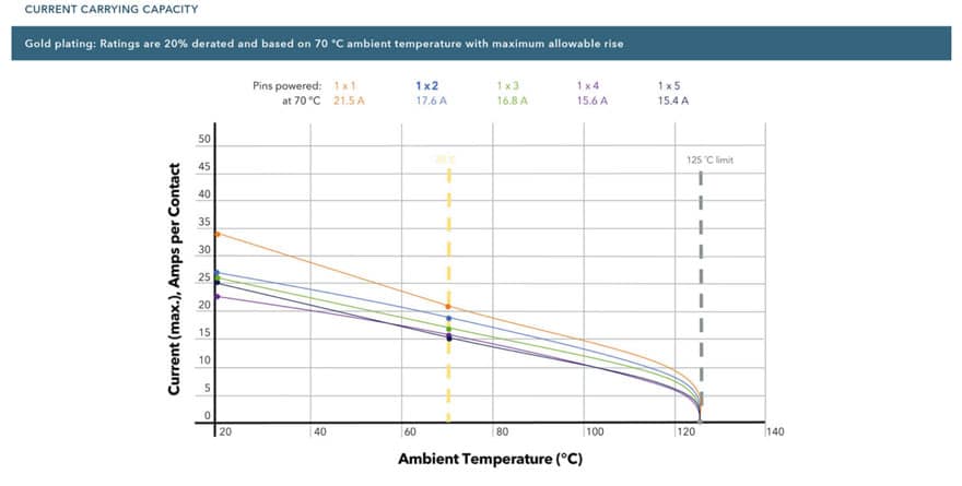
Figure 1. Connector derating chart example of power connectors; source: Samtec

In the example on Figure 1. shown here, we can see that an ambient temperature of 70°C requires that we reduce the current passing through the contact by 20%. Placing this information into a hypothetical real-world installation, we can see that external conditions play an important role in the performance of connectors. 

We also need to consider the published operating temperature of the connector itself. This will often be limited by the materials used in the connector’s design, in particular the plastic used for the insulator. In our hypothetical example, the operating temperature range of the connector might be 125°C, typical for a connector fitted with gold-plated contacts. There are also connector types with tin-plate contact finishes as a more cost-effective option. However, it is important to note that the operating temperature for tin-plated contacts is lower. 

Solving the Temperature Problem

There are several solutions to the problem of temperature and current ratings. The simplest approach is to use a connector with larger contacts. One of the key factors governing the current rating of an electrical terminal is its mass. A larger terminal with more material should have a lower resistance and be able to carry more power. However, as we are trying to find solutions for the compact designs of the future, a larger connector is not always convenient.

Another way to solve the problem is to use a connector with a larger pitch. Pitch is the term used to describe the distance between terminals within electrical and electronic components. A greater pitch will aid in the dissipation of heat, which should lead to a reduced temperature rise for a given current. However, this is also will result in a larger connector, which does not solve our design problem.

The thoughtful approach is to consider the contacts themselves. Conventional designs comprise a fixed male contact that is inserted into a socket or female. The mating area of the female terminal is split or bifurcated, and the two parts provide a constant force to ensure electrical continuity. The actual area of contact between the two terminals is small. However, alternative contact designs allow greater performance.

Related

Source: Samtec

Recent Posts

How to design a 60W Flyback Transformer

12.5.2025
31

Würth Elektronik Offers New Power Supplies Development Kit

29.4.2025
44

Non-Magnetic Interconnects

23.4.2025
14

DigiKey Announces Sponsorship of KiCad to Support Open-Source EDA Development

9.4.2025
12

Impedance Matching with RF LC Circuits 

20.3.2025
187

DigiKey Partners with SparkFun to Equip Young Engineers with XRP Robotics Kits

18.3.2025
16

10 Tips for Ensuring Reliability of Discrete Wire Assemblies

20.2.2025
50

Polymer Materials and Processing

31.1.2025
35

Fly-Buck Converter Explained and Comparison to Flyback

2.4.2025
407

RLC Circuit Switching Response Explained

2.5.2025
492

Upcoming Events

May 28
16:00 - 17:00 CEST

Power Over Data Line

View Calendar

Popular Posts

  • Buck Converter Design and Calculation

    0 shares
    Share 0 Tweet 0
  • Boost Converter Design and Calculation

    0 shares
    Share 0 Tweet 0
  • Flyback Converter Design and Calculation

    0 shares
    Share 0 Tweet 0
  • LLC Resonant Converter Design and Calculation

    0 shares
    Share 0 Tweet 0
  • Why Low ESR Matters in Capacitor Design

    0 shares
    Share 0 Tweet 0
  • Ripple Current and its Effects on the Performance of Capacitors

    3 shares
    Share 3 Tweet 0
  • SEPIC Converter Design and Calculation

    0 shares
    Share 0 Tweet 0
  • What is a Dielectric Constant and DF of Plastic Materials?

    4 shares
    Share 4 Tweet 0
  • How to Select Ferrite Cores

    0 shares
    Share 0 Tweet 0
  • Guide to Snubber Capacitors

    0 shares
    Share 0 Tweet 0

Newsletter Subscription


Passive Components Blog

© EPCI - Leading Passive Components Educational and Information Site

  • Home
  • Privacy Policy
  • EPCI Membership & Advertisement
  • About

No Result
View All Result
  • Home
  • Knowledge Blog
  • Premium Suppliers

© EPCI - Leading Passive Components Educational and Information Site

This website uses cookies. By continuing to use this website you are giving consent to cookies being used. Visit our Privacy and Cookie Policy.
Go to mobile version