source: ECN article
Mon, 06/06/2016 – 2:39pm by Kory Schroeder, Director of Marketing & Product Engineering, Stackpole Electronics
With improvements in manufacturing and materials technology, resistor manufacturers have been able to increase the rated power for a given chip size. These higher power resistors can be an effective way to downsize or to add functionality to circuit designs, but understanding the relationship between the working voltage rating and power rating is vital.
“Critical resistance value” is defined as the resistance value at which a particular part may operate at both full rated power and full rated voltage. Most resistor manufacturers specify a maximum working voltage in addition to the power rating. The relationship between working voltages and power ratings significantly impacts a resistor’s function at the low end and high end of the value range. This relationship applies to all resistors regardless of technology or manufacturer.

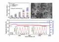
From this data, it is clear that only at exactly 56.25K ohms can the 0603 resistor handle both 75 volts and 0.1W simultaneously. While this is of some interest for all resistors, it is most important when dealing with high value and high voltage resistors, or low resistor values such as current sensing and wirewound resistors.
Current Sense Resistors and Wirewounds
Current sensing resistors are focused on the regulating and monitoring of power from a supply to an end device. With rapidly expanding component design technologies, current sensing resistors are used for a wide variety of handheld electronic devices, power supplies of all types, and LED drivers.
When an application requires dissipating more than 5 watts of power for an extended period, wirewound resistors are often the logical choice. These resistors are known for their ability to withstand high amounts of current and remain electrically and environmentally stable. Wirewound resistors feature several parameters that are adjustable. This gives them advantages over film resistors.
Current sense and wirewound resistor data sheets often don’t have a working voltage specified on them at all. This is primarily due to the fact that these series only offer low resistance values where the amount of electrical energy the part can withstand is determined only by the power rating. For example, using the general purpose 0603 chip resistor graph above, if this part were only available in resistance values below 50K ohms, then the voltage rating of 75 volts would be meaningless; you could never actually apply 75 volts to the part continuously because that would exceed the power rating.
For wirewound resistors, some of the most challenging applications are those that require high voltage handling. Because wirewound resistors typically only offer low resistance values, any application using wirewounds that must withstand high voltage transients requires that the element wire be uniquely specified for that purpose.
High Voltage Resistors
Critical resistance value is extremely important to high voltage resistors. High voltage requirements typically correspond to high resistance values and vice versa. The reason for this is Ohm’s law and the power equation for voltage. Put simply, high voltage across a low resistance value would cause an unreasonable amount of power to be generated. This in turn would require a very large resistor to dissipate the energy and would probably exceed the product’s capabilities.
Occasionally customers will assume that since a certain resistor is defined and designed for high voltage applications, the working voltage rating applies to all resistance values for a given size. The above graph shows that although the numbers have changed significantly compared to the general purpose 0603, the relationship is still the same. Since the high voltage 2512 size resistor offers resistance values below 4.5Meg ohm (the critical resistance value), it is important to realize that these resistance values will not handle the full rated working voltage continuously without violating the power rating of the device. Since many high voltage applications require high resistance values, this typically is not an issue.
The resistor market has responded with technological advances and improvements to attempt to meet whatever the power system design requires. Power systems continue to push the technological envelope for higher power ratings, better electrical stability, smaller chip sizes, and of course lower component costs. However, when specifying resistors, one of the most important factors to understand is the critical resistance values and how they relate to power and voltage. In short, the amount of electrical energy the part can withstand is determined by the maximum power rating. Selecting a resistor that can handle the rated power without exceeding the maximum working voltage is vital in every power system. Choosing a resistor without this data can lead to degradation of the resistor and catastrophic failure of the power system and the electronic device.