Passive Components Blog
No Result
View All Result
  • Home
  • NewsFilter
    • All
    • Aerospace & Defence
    • Antenna
    • Applications
    • Automotive
    • Capacitors
    • Circuit Protection Devices
    • electro-mechanical news
    • Filters
    • Fuses
    • Inductors
    • Industrial
    • Integrated Passives
    • inter-connect news
    • Market & Supply Chain
    • Market Insights
    • Medical
    • Modelling and Simulation
    • New Materials & Supply
    • New Technologies
    • Non-linear Passives
    • Oscillators
    • Passive Sensors News
    • Resistors
    • RF & Microwave
    • Telecommunication
    • Weekly Digest

    Smolteks CNF MIM Capacitor Break 1 µF/mm²

    Samsung Electro-Mechanics Releases 0201 X7T 1uF 6.3V MLCC for ADAS Applications

    Murata Announces 0402 Automotive Chip Ferrite Beads for V2X

    2025 Thick and Thin Film Resistor Networks Environment Overview

    Role of High-Q Ceramic Filters to Overcome GNSS Jamming

    Optimization of IoT for GEO NB-NTN Hybrid Connectivity

    TDK Releases Automotive Power-Over-Coax Inductor for Filters

    Advanced Conversion Announces Mass Production of 200C Film Capacitors

    VinaTech Supercapacitors: Enhancing Smart Meter Reliability and Efficiency

    Trending Tags

    • Ripple Current
    • RF
    • Leakage Current
    • Tantalum vs Ceramic
    • Snubber
    • Low ESR
    • Feedthrough
    • Derating
    • Dielectric Constant
    • New Products
    • Market Reports
  • VideoFilter
    • All
    • Antenna videos
    • Capacitor videos
    • Circuit Protection Video
    • Filter videos
    • Fuse videos
    • Inductor videos
    • Inter-Connect Video
    • Non-linear passives videos
    • Oscillator videos
    • Passive sensors videos
    • Resistor videos

    Understanding Switched Capacitor Converters

    Coupled Inductors Circuit Model and Examples of its Applications

    Inductor Resonances and its Impact to EMI

    Highly Reliable Flex Rigid PCBs, Würth Elektronik Webinar

    Causes of Oscillations in Flyback Converters

    How to design a 60W Flyback Transformer

    Modeling and Simulation of Leakage Inductance

    Power Inductor Considerations for AI High Power Computing – Vishay Video

    Coupled Inductors in Multiphase Boost Converters

    Trending Tags

    • Capacitors explained
    • Inductors explained
    • Resistors explained
    • Filters explained
    • Application Video Guidelines
    • EMC
    • New Products
    • Ripple Current
    • Simulation
    • Tantalum vs Ceramic
  • Knowledge Blog
  • Suppliers
    • Who is Who
  • Events
No Result
View All Result
Passive Components Blog
No Result
View All Result

Current Sense Monitoring Circuits — More Important Than Ever

24.8.2022
Reading Time: 4 mins read
A A

To facilitate that control design, engineers require accurate and speedy current sense measurement. Monitoring power to a motor can also greatly improve system reliability, as an increase in current draw may indicate a need for maintenance long before a breakdown occurs.

The world is going electric. Thomas Edison and Nikola Tesla would be happy to see a move toward electric transportation of all kinds. Advanced battery systems are powering those vehicles, stabilizing the grid and opening many new opportunities. Engineers developing automotive systems, along with those designing industrial automation and robotics, are moving to a higher level of design with more precision motor control circuitry and more complex motion algorithms that yield better control and efficiency.

RelatedPosts

Smolteks CNF MIM Capacitor Break 1 µF/mm²

Samsung Electro-Mechanics Releases 0201 X7T 1uF 6.3V MLCC for ADAS Applications

Murata Announces 0402 Automotive Chip Ferrite Beads for V2X

The most cost-effective and reliable method of monitoring current is the precision shunt resistor. There are two less common methods to measure current. One uses a Hall Effect sensor to measure the flux field generated by a current. While this has the advantage of low insertion loss, it is somewhat expensive and requires a rather large amount of PCB real estate. The other method, using a transformer to measure induced AC current, is also size and cost intensive, and is useful only for AC circuits.

Features

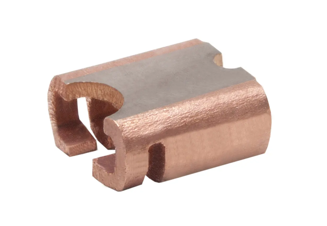
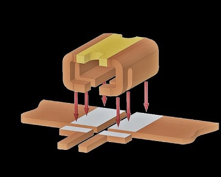
A recent introduction from Isabellenhütte (pronounced Iz-a-bell-en-HOOT-eh) is the BVN 1216 surface mount current shunt. This resistor series offers 1.0 (mΩ) or 0.5-mΩ milliohm values and features a small (4.1 x 3.1 x 1.9 millimeter) package. The four-terminal device handles 100 amperes continuously ( 0.5-mΩ version) and is available with 1 or 5 percent tolerance. Very important in this type of device is the TCR, which for the BVN is <50 parts per millions per degrees Celsius. The 0.5-mΩ version is rated at 5 watts up to 130° C — de-rated to 170° C. The 1-mΩ version is rated at 3 watts. The resistors also have very low inductance — less than 2 nano-henries (nH) — and they are AEC-Q200 qualified with reliability testing for temperature cycling, shock, vibration and moisture resistance. Their package aids airflow around the resistive element and they can be mounted on a direct bonded copper (DBC) or insulated metal substrate (IMS) power substrates.

Figure 2: The BVN Surface Mount Shunt Resistor. Source: Isabellenhütte USA
Figure 1: The BVN Surface Mount Shunt Resistor. Source: Isabellenhütte USA

The very low ohmic values are obviously great for cutting power loss. A good sense amplifier will be necessary to work with the accompanying low voltages. The BVN sense resistors are often used for currents in the range of 5-80 amps, and there are a number of current sense amplifiers available that make it easy to design a full measurement circuit.

These ICs have highly matched internal resistors, which is important to minimize gain and common mode voltage errors. Current sense amplifiers usually come preconfigured to voltage gains — keeping those resistors internal. For example, the INA199 from Texas Instruments is available with gains of 50, 100 or 200. The IC can sense drops across shunts at common-mode voltages from 0.3 to 26 volts, independent of its supply voltage.

A designer can choose to sense the current on the low side of the power delivery; however, placing a resistor in the load’s path to ground means that ground is floating at a slightly higher potential than the system ground. This arrangement can cause problems with ground loops. Current sense amps need to have a high CMRR if they are used on the high side.

Since the INA199 has a low offset voltage and a Zerø-Drift architecture, it enables current sensing with full-scale drops across the shunt as low as 10 millivolts (mV). Additionally, the parts common-mode rejection ratio is 100 decibels (dB) minimum, 120 dB typical, so the errors from high-side monitoring are tolerable. Offset voltage is typically 5 microvolts (µV). Gain error is 0.03 percent typical and 1 percent maximum over a temperature of 40° C to 125° C. The ICs operate from a single +2.7 to +26-volt power supply, drawing a maximum of 100 microamperes (µA), and come in both SC70 and thin UQFN-10 packages.

Figure 3: Typical power steering system. Source: Saginaw Future Inc. / CC BY 2.0
Figure 2: Typical power steering system. Source: Saginaw Future Inc. / CC BY 2.0

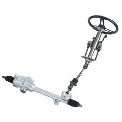
One current-sensing example application is automotive power steering motor control. The steering wheel connects via a CAN or LIN bus to a microcontroller and a bidirectional brushless DC motor drive. Both the position and the torque of the steering wheel are measured. The microcontroller then drives the steering motor as necessary and uses the average current to the motor, as measured by a shunt resistor, to determine torque and a position sensor to determine steering angle.

Often, each of three phases of the BLDC motor are monitored with separate shunt resistors. Peak current to this motor can be 50 amps, and both excellent stability and low inductance are required for this shunt.

Just as in automotive, precision shunt resistors are used in motor controllers, fuel injection, ignition, lighting, water pump, transmission and locking systems.

Related

Source: Electronics 360

Recent Posts

Samsung Electro-Mechanics Releases 0201 X7T 1uF 6.3V MLCC for ADAS Applications

19.6.2025
1

Murata Announces 0402 Automotive Chip Ferrite Beads for V2X

19.6.2025
5

2025 Thick and Thin Film Resistor Networks Environment Overview

19.6.2025
2

TDK Releases Automotive Power-Over-Coax Inductor for Filters

18.6.2025
6

Bourns Introduces New Automotive Grade BMS Signal Transformer

17.6.2025
6

YAGEO Releases High-Sensitivity Residual Current Detectors for Safer EV Charging

17.6.2025
9

YAGEO Releases High Isolation Transformer for 1500VDC Applications

12.6.2025
23

Murata Releases Worlds First Molded Thermistor with Wire-Bonding

12.6.2025
17

Vishay Extends Axial Wirewound Resistors with WSZ Lead Form

12.6.2025
13

Smoltek CNF-MIM Capacitor Commercialization Update

11.6.2025
29

Upcoming Events

Jun 24
16:00 - 17:00 CEST

Limitations of PSFB converters and improvements by a variable inductor ft. Sam Ben-Yaakov

Jun 24
17:00 - 18:00 CEST

Ultra-Compact and Efficient Switched-Capacitor Power Converters

Jul 23
13:00 - 14:00 CEST

PCB design for a Smartwatch

View Calendar

Popular Posts

  • Buck Converter Design and Calculation

    0 shares
    Share 0 Tweet 0
  • Boost Converter Design and Calculation

    0 shares
    Share 0 Tweet 0
  • Flyback Converter Design and Calculation

    0 shares
    Share 0 Tweet 0
  • What is a Dielectric Constant and DF of Plastic Materials?

    4 shares
    Share 4 Tweet 0
  • LLC Resonant Converter Design and Calculation

    0 shares
    Share 0 Tweet 0
  • Ripple Current and its Effects on the Performance of Capacitors

    3 shares
    Share 3 Tweet 0
  • How to Design an Inductor

    0 shares
    Share 0 Tweet 0
  • SEPIC Converter Design and Calculation

    0 shares
    Share 0 Tweet 0
  • Dual Active Bridge (DAB) Topology Explained

    0 shares
    Share 0 Tweet 0
  • Flying Capacitors Explained

    0 shares
    Share 0 Tweet 0

Newsletter Subscription


Passive Components Blog

© EPCI - Leading Passive Components Educational and Information Site

  • Home
  • Privacy Policy
  • EPCI Membership & Advertisement
  • About

No Result
View All Result
  • Home
  • Knowledge Blog
  • Premium Suppliers

© EPCI - Leading Passive Components Educational and Information Site

This website uses cookies. By continuing to use this website you are giving consent to cookies being used. Visit our Privacy and Cookie Policy.
Go to mobile version