


Measuring voltage across known resistor seems to be a simple task. Nevertheless there are some considerations and tradeoffs that has to be bear on mind for a proper and reliable design of current-sense shunt resistor as described in article by Bill Schweber published by EE Worldonline.
Sizing the current-sense resistor
It begins with V = IR
It’s necessary to measure current flow to a load or into and out of a battery in many designs. There are several ways to do this, and among the most widely used is via a sense resistor. The idea is simple: insert a resistor of known value in series with the current-carrying lead, measure the voltage drop across it, do the simple I = V/R math (which can be done digitally but is often accomplished with an analog circuit), and you’re done (Figure 1). (Note: this in-line series resistor is often called a “shunt” resistor which is a misnomer, as a true shunt is in parallel with a load.)

This sensing solution seems fairly straightforward, and it is – in theory. But engineering design is where principle meets reality and where the balancing decisions are made. The obvious question here is what value of resistance to use for that resistor, and that’s where the tradeoffs begin:
- On one side, a larger resistor makes the voltage reading easier and provides higher resolution as it increases the dynamic range and improves signal/noise ratio (SNR) of the voltage reading.
- However, that larger-value resistor also “robs” the load of available rail voltage, as the drop subtracts from the power-rail voltage to the load. Therefore, a smaller resistor is better in terms of minimizing loss of available voltage to the load.
Some basic math shows the dilemma. Consider a 5-V rail delivering a modest 2-A maximum to the load, both reasonable mid-range values. A 100-mΩ resistor will produce a maximum 200-mV drop, and that is not a large value to work with when you are trying to measure current to, say, 1% (here, 2 mV) in the presence of noise and other circuit issues. Also, that 200 mV drop represents 200 mV/5V = 0.04 or 4% of the rail, which is a lot to “give away.”
Further, a resistor in the output loop from source through load to ground (or circuit common) can compromise the loop dynamics and transient response. The source and its controller see that resistor as part of its load, but it is not part of the real load the source is trying to supply (designated “Load” in Figure 1). There’s a mismatch between what the source perceives as its load and the true load, which can impact the anticipated versus real performance. Any power dissipated by the resistor (P = I2R) adds to system inefficiency as well.
So the sense-resistor dilemma is clear: a higher resistance value results in a larger voltage drop (good for measuring) but also “steals” more of the rail’s maximum voltage that can be delivered to the load, adversely affects output-loop dynamics and decreases efficiency (all bad).
What’s a “rule of thumb” starting point for how much voltage drop should be acceptable and the corresponding resistance value? It turns out that across a wide range of situations ranging from low-voltage/low current designs to much higher ones, a 100-mV drop seems to be a good starting point. Given this voltage drop and the maximum current, it’s straightforward to calculate the correct resistance value.
What resistor values are commonly used for current sensing? It may be a surprise for designers who are used to selecting resistors of 1, 10, or even 100 kilohms. Do the math, and you’ll see that resistors are usually below one ohm and often go well below that value into the single-digit milliohm range and even lower. These “oddball” values are so widely used that they are standard components available in many configurations and ratings from multiple vendors.
There’s more to the story than just picking a resistor with a low value, as the impact on reading resolution, SNR, and wasted rail voltage is just one aspect of the problem. The other consideration is also important but somewhat more difficult to assess:
Self-Heating Effect
The self-heating on the sense resistor value is happening due to temperature coefficient and resultant drift. The thermal impact related to resistor I2R self-heating power dissipation is significant and plays into the integrity of the reading as well as resistor selection.
This unavoidable self-heating has several negative consequences:
- it represents heat, which adds to the system’s thermal load and so must be managed and removed.
- it represents wasted power and reduced efficiency, thus reducing runtime in battery-powered products.
- and perhaps less apparent but especially critical, the heat causes a rise in temperature of the current-sensing resistor, which changes the resistor’s value and thus affects the credibility of the current determination (which is determined by the voltage reading across that “known” resistor).
This last factor is often ignored, at least at first, since it’s easy to assume that a fixed-value resistor is just that. The numbers show the impact as defined by the resistor’s temperature coefficient of resistance (tempco). The dissipation of even a small-value resistor with modest current can cause significant drift from nominal value.
This is another reason designers try to use as small a resistor value as possible, commensurate with delivering a sufficient voltage drop for a viable reading. Note that since dissipation is proportional to the square of the current, it would be more effective to reduce the current, but that is set by the system load and cannot be changed.
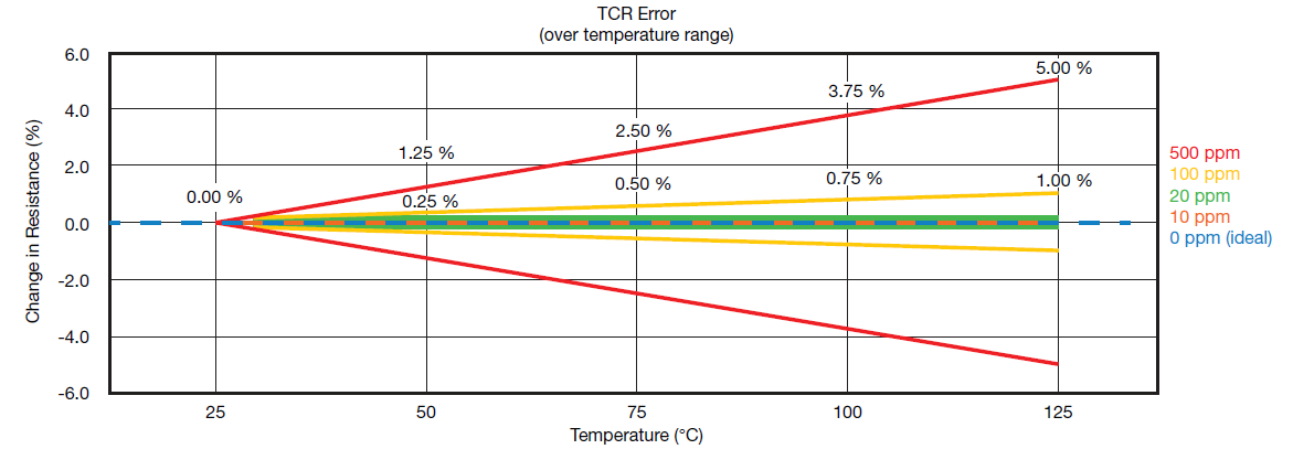
Consider a 1-A current and a 1-Ω resistor, so the heat dissipation is 1 watt. For a physically small resistor, that’s enough to cause the temperature to rise by tens of degrees, depending on where and how the resistor is positioned, airflow, and other factors. That’s why a resistor’s datasheet includes a specification for temperature coefficient of resistance, usually expressed as change in parts per million per degree Centigrade (ppm/°C) or percent/per degree Centigrade (%/°C). A tempco of 1000 ppm/°C equals 0.1%/°C.
Going through the numbers, temperature rise can have a major impact on resistance value, Figure 2. Consider a standard resistor used in non-critical circuits, having a tempco of around 1000 ppm/°C or 0.1%/°C. A rise of 50°C results in a resistance change of 5%, while a possible rise of 100°C results in a 10% change. This can be excessive in many applications.
As the needed resistance value in so many designs is so small – often well below one ohm – it may seem that a quick, easy, and “free” solution to having a sense resistor is to just use a short length of the PC-board copper trace, with its size calculated to provide that exact resistance value. However, ordinary copper, such as used for PC cladding, has a typical tempco of 4000 ppm/°C or 0.4%/°C, which means any self-heating – aggravated by ambient board and product heat – will result in large drift and errors. In contrast, normal tolerance on the PC-board track width, length, and copper thickness would add to the initial error. Thus, the PC-board trace technique is only used where accuracy demands are very loose.
Sense resistors meet the need
The designer has several options in selecting a resistor which will not drift excessively in the application:
- Choose a higher wattage resistor which can dissipate the power with less temperature rise.
- Choose a resistor specifically designed for this function, with much lower inherent tempco drift.
The right choice depends on the situation, and many designers choose the second option. Although low-tempco resistors are costly, they require less board space and have greater assurance of consistent results.
Vendors offer families of low-ohm, low-tempco standard resistors with a range of power ratings. A typical “low tempco” resistor will have a tempco value around 100 ppm/°C, and there are more costly ones available with tempcos down to 10 to 20 ppm/°C and even 1 ppm/°C for precision situations (at an even higher cost, of course). But in applications where “coulomb counting” and power management are critical, the cost may be well worth it.
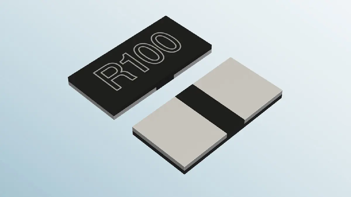
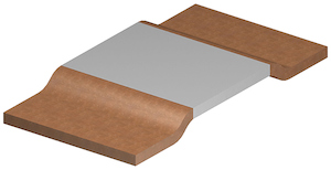
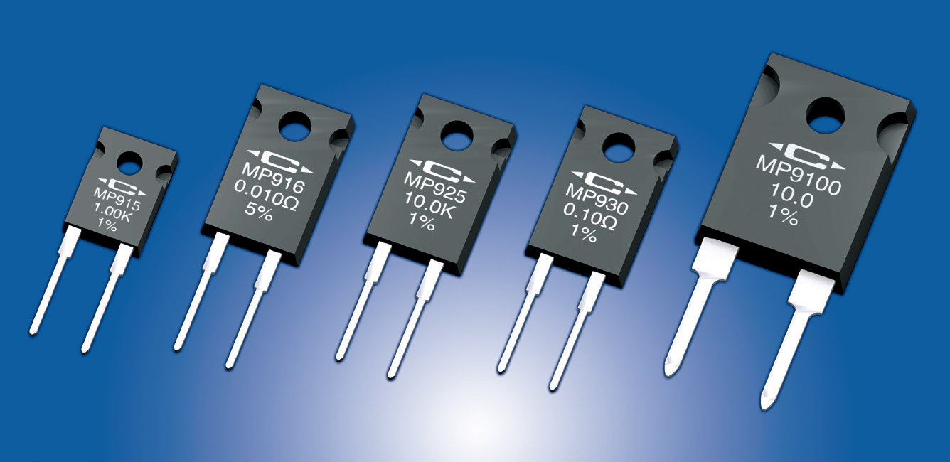
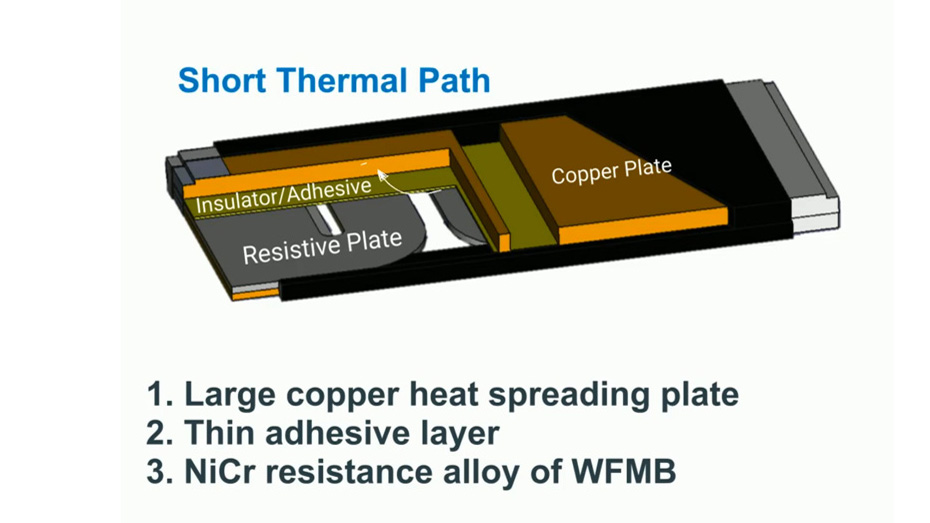
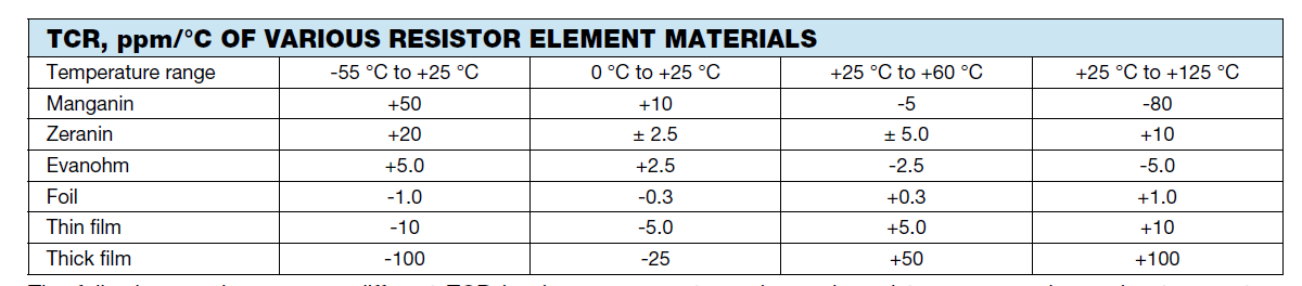
Some of these current-sense resistors are best suited for DC and low-frequency applications only, while others are specially designed to have low self-inductance and so can be used at higher frequencies. Current sense resistors, especially at high power ratings, often do not look like standard “chip” resistors but instead look like plain metal strips or power devices (Figures 3, 4 and 5). They are made using highly specialized materials and proprietary fabrication techniques. Their tempcos are carefully controlled and measured, and to add to the design-analysis challenge, those tempcos are not constant over the entire operating range (Figure 6).
Among the many vendors of these resistors are Vishay Intertechnology, TT Electronics, Riedon, Bourns, New Yorker Electronics, Ohmite, Caddock Electronics, Stackpole, KOA Speer, Isabellenhutte and Rohm, with most offering values well below even one milliohm up to several ohms, and with power ratings from a fraction of a watt to kilowatts. When using these ultralow-resistance values, keep in mind that how contact will be made and connection resistance of the wires or PC board to the sense resistor must be added to the design analysis.
Conclusion
The apparently simple issue of how to sense current using a resistor is a good example of finding an optimal balance point among engineering tradeoffs in an easy-to-explain situation. There are many available options when sizing the resistance ohm value, temperature coefficient, and power rating. Even so, making those sizing decisions is only part of the complete solution, as there are also issues related to the electronics, which sense that voltage, Kelvin connections, high common-mode voltage, ground loops, isolation, and even safety considerations.
featured image source: ROhm


