


Source: EPCI e-Symposium PCNS paper
by Alexander Teverovsky; Jacobs Technology Inc. NASA GSFC, USA
BEST PAPER AWARD BY PCNS ATTENDEES
presented by A.Teverovsky at the 2nd PCNS 10-13th September 2019, Bucharest, Romania as paper 5.1.
Introduction
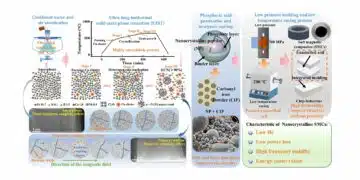
One of the major benefits of chip polymer tantalum capacitors (CPTCs) compared to conventional MnO2 capacitors is reduction of the equivalent series resistance (ESR). Reduction of ESR improves the efficiency of parts for filtering in power lines and decreases self-heating in capacitors resulting in lower operating temperatures and probability of failure. A substantial improvement in performance of tantalum capacitors was achieved with introduction of conductive polymers based on poly(3,4-ethylenedioxythiophene), PEDOT [1], as a cathode materials.
Manganese oxide has resistivity ~1 ohm_cm, while the resistivity of PEDOT based compositions that are conjugated polymers with p-type conductivity is approximately 10 times less. A breakthrough technology was achieved by introducing a water-soluble poly-styrene sulfonate (PSS) in the polymer composition and formation of pre-polymerized PEDOT:PSS systems.
Pre-polymerized conductive polymers have a better thermal stability compared to the in-situ polymerized PEDOT films [2] and allow for production of capacitors with high voltage ratings, up to 125 V, that could not be realized with MnO2 technology [3]. A better performance and improved quality and reliability of CPTCs that had been achieved over the last years made these parts not only preferred components for many commercial applications, but their employment has begun in reliability-demanding automotive, medical, military and space systems [4].
One of the major drawbacks of CPTCs compared to MnO2 capacitors is poor long-term stability. The conductivity of PEDOT:PSS polymers decays with time at high relative humidity or high-temperature storage in dry conditions [5, 6] resulting in degradation of CPTCs under environmental stresses, in particular, during long-term storage at high temperatures and under combined stresses of temperature and humidity [3, 7].
Until recently, operating temperature of CPTCs was limited to 85 °C or 105 °C, and given the limitations of conductive polymer materials, it appeared unlikely that the upper limit would be increased significantly in the near future [8]. However, in 2014 KEMET and AVX introduced automotive grade capacitors that can pass biased testing at 85 °C and 85% RH for 1000 hours and unbiased storage at 125 °C for 1000 hours. This had been achieved by development of new materials and processes [9], and improvements in the packaging system [1].
A certain level of ESR degradation and failure caused by environmental stresses occurs also in MnO2 tantalum capacitors. However, manganese dioxide has no intrinsic degradation during environmental stresses, and parametric ESR failures of MnO2 capacitors are typically caused by delaminations and increased resistances at the interfaces between cathode layers (MnO2/carbon or carbon/silver epoxy). These failures are often due to insufficient margins between the specified maximum and actual values of ESR [10].
In this situation, even relatively minor changes in compressive stresses caused by moisture-related swelling or baking-related shrinking of molding compounds might change the level of delamination or cracking between the cathode layers resulting in ESR variations. These variations occur mostly during the relatively short periods necessary to stabilize moisture content in the package. Although MnO2 capacitors are specified for a temperature range from -55 ºC to +125 ºC, and no storage life testing is required even for military grade capacitors, experiments show that these parts are thermally stable and can sustain 1000 hour storage at 150 ºC and even 175 ºC [7].
Contrary to MnO2 capacitors, specifications for CPTCs include a requirement for high temperature storage (HTS) testing that is typically carried out at 125 ºC for 1000 hours (Automotive Electronics Council, AEC-Q200 requirements). Some general purpose capacitors do not have HTS requirements and some are tested for 2000 hours at 105 ºC. Manufacturers specify ESR values for the post-HTS measurements for commercial parts, but automotive industry capacitors (AEC-Q200) and military specifications (e.g. DLA DWG #04025) do not have requirements for ESR after environmental stresses.
According to manufacturers’ specifications, post-HTS values of ESR are relaxed substantially compared to the initial limits, from 2 to 5 times. This easing of requirements reflects intrinsic degradation processes in polymer cathode materials, and requires assessments of the end-of-life characteristics at application conditions. Although significant efforts have been made to assure stability of ESR during 1000 hours testing at 125 ºC, there is still no answer to the question about long-term (years) stability of the parts at operating temperatures.
In this work, different types of polymer capacitors from three manufacturers have been stored at temperatures from 100 ºC for periods up to 18,500 hours to 175 ºC for up to 2000 hours to reveal common features in their behavior and develop reliability models. Characteristics of capacitors have been measured periodically during the storage. Parameters describing degradation of ESR during HTS have been approximated using a Weibull-Arrhenius model that allowed for predictions of the ESR values at operating temperatures. Possible mechanisms of degradation and the effect of packaging are discussed.
Experiment
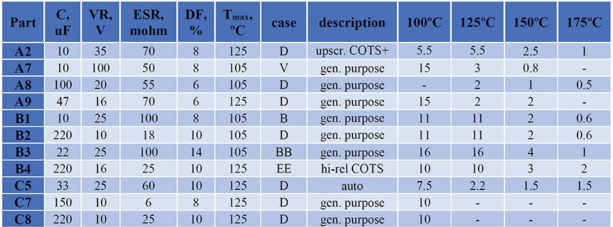
Four types of Mfr.A, four types of Mfr.B, and three types of Mfr.C capacitors have been used in this study. Characteristics of CPTCs, including capacitance (C), rated voltage (VR), maximum ESR, dissipation factor (DF) and maximum operating temperature, as well as the case size and quality levels are shown in Table 1.
Different groups of capacitors, from 5 to 20 samples in each (typically 10 samples), have been stored at 100 ºC, 125 ºC, 150 ºC, and 175 ºC, and their AC characteristics including capacitance and dissipation factors at 120 Hz and ESR at 100 kHz have been measured periodically. Duration of testing varied from 18,500 hours at 100 ºC to 1000 hours at 175 ºC as indicated in the last four columns in Table 1.
Table 1. Characteristics of capacitors. Numbers in columns from 100 ºC to 175 ºC indicate duration of testing in kilo hours.
Test results
Variations of ESR with time of storage
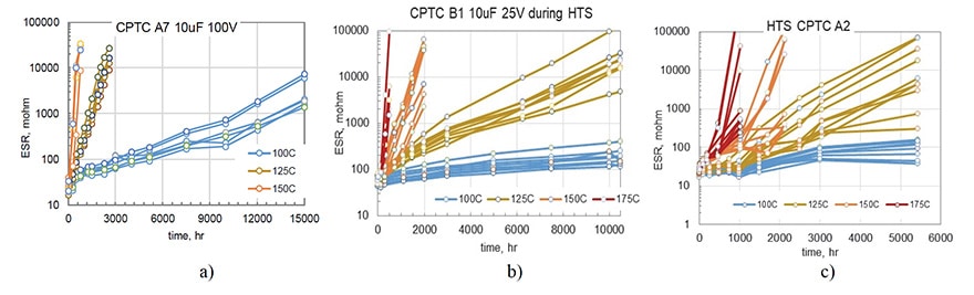
Typical results of ESR variations with time of storage at different temperatures are shown in Fig.1. In spite of some spread of data, there is a clear effect of temperature on the rate of degradation for all capacitors. In most cases, ESR increased with time exponentially.
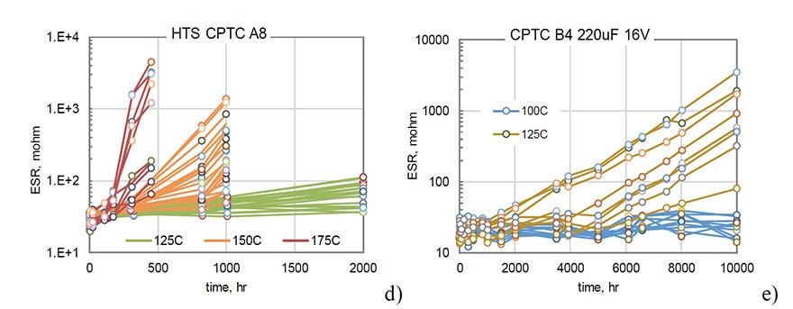
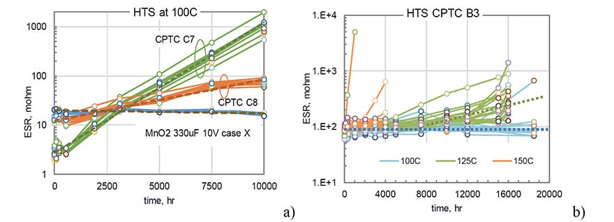
A comparison of ESR variations during long-term (10,000 hours) storage at 100 ºC for two types of polymer capacitors C7 (150 mF) and C8 (220 mF) and one type of MnO2 capacitors (330 mF) rated to 10 V that was used as a reference is shown in Fig. 2a. Contrary to MnO2 capacitors that had stable ESR values, polymer capacitors degraded substantially, increasing up to 500 times for C7 and approximately 8 times for C8 after 10,000 hours of storage. Note that both types of CPTCs shown in Fig.2 have been produced by the same manufacturer and had similar packages (D case). However, the level of degradation was different by almost two orders of magnitude.
All samples in lots C7 and C8 degraded with a similar rate and variations of ESR with time allow for approximations with exponential functions. A similar exponential increase of ESR was observed for capacitors shown in Fig.1. However, for 19 out of 20 samples of B3 capacitors the values of ESR remained stable during 18,500 hours of HTS at 100 ºC, and an increasing trend at 125 ºC was observed only after ~8,000 hours (see Fig. 3b). At 150 ºC the majority of samples remained stable even during 4000 hours of HTS, and only 3 out of 20 capacitors had parametric ESR failures.
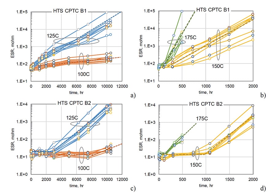
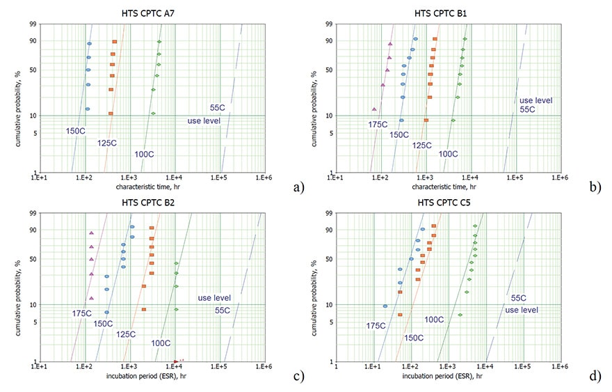
Results of HTS testing at different temperatures for B1 and B2 types of capacitors are shown in Fig.3. There is a certain delay time or incubation period, ti, before the inception of an exponential growth of ESR, and this time is decreasing with temperature. For B1 capacitors ti is ~1000 hours at 100 ºC and decreases to ~150 hours at 150 ºC and to less than 100 hours at 175 ºC.
The delay time depends on the part type and temperature, which is especially evident for B2 capacitors (Fig 3c and d). For these parts, ti decreases from ~ 8000 hours at 100 ºC to ~2500, ~900, and ~100 hours at 125 ºC, 150 ºC, and 175 ºC respectively.
Modeling of ESR degradation
ESR failures can be model based on analysis of distributions of times to failure (TTF), but this approach requires extended testing until a sufficient number of failures occurs. At temperatures close to operational, a very long time might be necessary to precipitate failures. Considering specifics of ESR variations with time, it is possible to simulate ESR degradation and predict possible ESR values at the end of the mission before a formal failure happens.
In a general case, degradation of ESR during storage can be described as an exponential growth with time that begins after an incubation period ti. The rate of ESR degradation can be described using a characteristic time t:
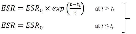
(1)
where ESR0 is the initial value of ESR.
Both parameters, t and ti, are assumed to reduce exponentially with temperature and their distributions can be approximated with the Weibull-Arrhenius models. The major parameters of these models are activation energies, scale factors, and slopes of the distributions:
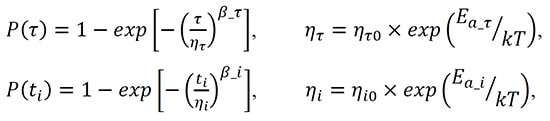
(2)
(3)
where ητ and ηi are the scale parameters, b_t and b_i are the slopes of the relevant distributions, and ητ0 and ηi0 are constants.
Examples of distributions of t and ti for four types of capacitors are shown in Fig.4 and validate application of the Weibull-Arrhenius model. Note that estimations of t and ti for a given sample required at least three data points at t > ti and at t < ti. Due to a spread of ESR data that might be especially significant for capacitors with low ESR, accurate estimations of ti had been carried out for a few cases only.
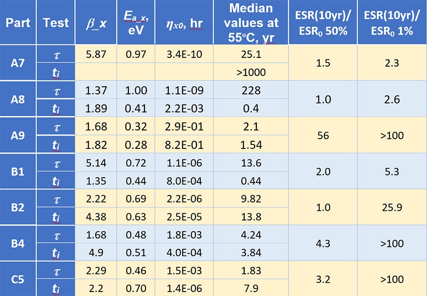
Parameters of the model Eq. (1 – 3) calculated for different types of capacitors and characteristics calculated for the use temperature (55 ºC ) are displayed in Table 2. Variations of the models’ parameters for different part types is significant, for example, the activation energies for characteristic times vary from 0.32 to 1 eV and the median characteristic time from 1.83 to 228 years.
Using these data the level of ESR increasing at the end of the mission was estimated. Two last columns show how many times ESR will increase by the end of a 10 year mission compared to the initial ESR values (the ratio of ESR at the end of a 10 year mission at 55 ºC to the initial value for 50% and 1% of capacitors). For 50% of the parts this ratio varies from no change for B2 (ti > 10 years) and A8 (due to large t) to 56 times for A9 capacitors. The increase of ESR for 1 % of the parts is much larger and varies from the acceptable level of 2.3 to more than 100 times.
Table 2. Parameters of the model calculated based on distributions of the characteristic times (t) and incubation periods (ti).
Failure analysis
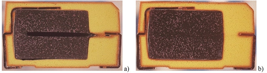
Cross-sectioning of two samples after 1000 hours of storage at 150 °C (see Fig.5) clearly shows discolorations in the molding compound (MC) that were caused by thermo-oxidative degradation of epoxy. Thin layers of brownish color along the surface of the case and the lead frame (LF) interface with MC indicate a diffusion-limited oxidation of MC.
Sample SN3 failed marginally at 200 mohm (Fig.5a) and SN1 failed catastrophically at 2 ohm (Fig.5b). Note that discoloration can be seen around the whole surface of the slug for SN1, whereas only a part of the surface close to the cathode portion of the lead frame had some discoloration in SN3.
A similar difference between the level of discoloration around the slug that correlated with the level of ESR degradation was observed in other part types. In all cases a less severe degradation after HTS corresponded to the absence of discoloration in molding compound at the internal areas around the slug. Obviously, these areas of discoloration in MC indicate the oxygen path towards the conductive polymer on the surface and inside tantalum slugs.
It is known that copper has a catalytic effect on degradation of polymer materials in general, and on epoxy resins in particular [11]. In the presence of a copper substrate, the rate of degradation and the relevant activation energy for epoxy adhesives decreases substantially. It is possible that the presence of copper LF facilitates thermo-oxidative decomposition of epoxy MCs, delamination, and enhances penetration of oxygen to the slug. Using LF based on copper alloys or materials having no copper, e.g. alloy 42, might improve stability of ESR for high-temperature applications.
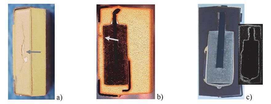
Several samples that had the worst degradation in the group were found to have cracks in the package (see Fig.6). A sample that failed after 1000 hours of HTS at 125 ºC at 200 mohm and had 440 mohm after 2000 hours of testing had a crack on a side of the package as shown in Fig. 6a. Another sample from this group (Fig. 6b) that failed parametrically after 200 hours of HTS at 150 ºC and catastrophically, at 2.67 ohm after 1000 hr had a crack under the anode terminal. Similarly, a sample from Gr. A7 that had a crack at the bottom of the package failed after 300 hr and had 2.4 ohm after 1000 hr of HTS at 150 ºC.
Discoloration of MC along the cracks shows that cracks provide a direct path for oxygen penetration and accelerate degradation processes substantially. Contrary to MnO2 capacitors, where cracks can facilitate some delaminations, but generally can be considered as cosmetic defects, cracking of the cases in polymer capacitors poses a serious reliability risk. Improvements in quality of packaging and a thorough control over the encapsulation process have been used by manufacturers to assure stability of automotive grade capacitors under environmental stresses [1].
Discoloration is obvious for CPTCs with light yellow MCs, and are much less obvious for parts encapsulated with black MCs. However, color analysis software allows for mapping of discolored areas in these parts as well (see Fig. 6c). Results indicate similar discoloration and degradation processes in all types of MCs used in CPTCs.
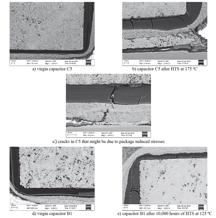
Degradation of ESR during HTS can be explained by two processes [7]: increasing of delaminations between different cathode layers and rising of the intrinsic resistivity of polymer cathode materials. Delaminations between different layers of conductive polymers, and especially between carbon layer and polymer are often observed even in virgin CPTCs, whereas vertical cracks are typical for parts after HTS (see Fig.7). In some cases, the crack propagates through silver paint and conductive polymer (see Fig. 7c) indicating that it was likely caused by stresses developed in the molding compound and transferred to cathode layers.
Both types of cracks are unlikely to cause a complete separation between the layers and increase ESR substantially. Due to a high conductivity of PEDOT:PSS polymers, even a relatively small contact area should be sufficient to assure low resistance of the interconnect [10]. The major mechanism of ESR degradation is thermo-oxidative processes in PEDOT:PSS compositions.
Discussion
It is commonly accepted that manganese oxide cathode tantalum capacitors do not have wear out mechanisms and typically fail catastrophically due to the presence of defects, so called infant mortality (IM) failures that result in substantially increased leakage currents or short circuits due to breakdown. The focus of the existing quality assurance system for MnO2 capacitors described in MIL-PRF-55365 is mostly on elimination of these IM failures and does not address AC parametric degradation sufficiently.
In particular, there is no requirements for high-temperature storage endurance testing. However, due to the intrinsic degradation of conductive polymers, HTS testing is necessary to assure that the time of inception of ESR failures at operating temperatures is greater than the intended mission time for the system. A common standard for HTS testing is 1000 hours at 125 ºC as it is described in AEC-Q200 requirements for automotive industry.
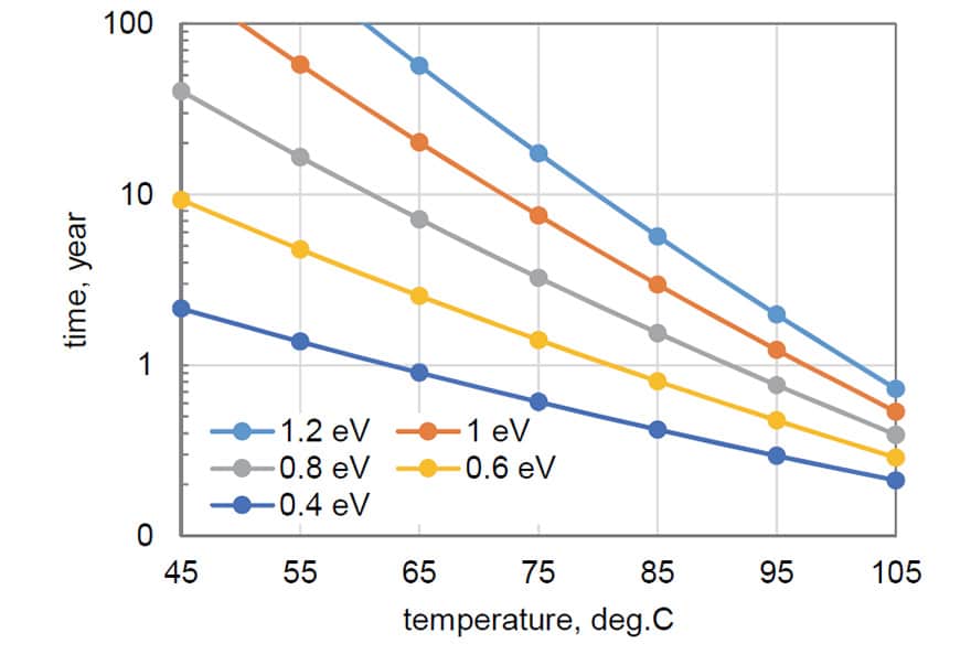
Knowing the activation energy of the degradation process, we can estimate the period of time this testing would be equivalent to at lower temperatures. Fig. 8 shows results of these estimations. A 1000 hours of storage at 125 ºC without failures (ESR remains below 3×ESRlimit) would be equivalent to more than one year of storage or operation at 55 ºC if Ea = 0.4 eV, and to more than 20 years at Ea = 0.8 eV.
Considering that these failures are due to wear-out processes, a relatively small number of samples would be sufficient to assure that the time to failure inception is greater than the mission time. However, the presence of defects in the case (cracks or LF/MC delamination) or their development with time of storage can reduce this time substantially.
To assure low probability of ESR failures a relatively large sample size is necessary. Considering uncertainties in stability of the materials and production processes during manufacturing of CPTCs, all lots should be tested using 77 samples (as per AEC-Q200) to qualify a specific lot of capacitors for hi-rel applications. Note that testing of 77 samples with no failures can assure that the probability of failure is likely below 1.5% which might be not sufficient for some hi-rel applications. Additional assurance can be achieved by a thorough visual examination during screening of the parts and after their soldering onto the boards.
For CPTCs used in space applications, thermo-oxidative degradation occurs mostly during the ground phase testing and integration periods. In general, activation energies of thermal degradation of polymers in vacuum are substantially greater than in the presence of oxygen [12].
Studies of thermal degradation of polystyrene (PS), polyethylene (PE), and polypropylene, (PP) in both inert nitrogen and air atmospheres showed that average activation energy of degradation reduced from ~2.3 eV in N2 to 0.7 eV in air for PE, from ~2.0 eV in N2 to 0.87 eV in air for PP, and from ~2.1 eV in N2 to 1.1 eV in air for PS [13].
Similar effects were observed for the conductive conjugated polymers. Testing of PEDOT:PSS organic solar cells showed that their stability was much better when the cells were kept in vacuum or dry nitrogen compared to air storage [14]. Thermal and thermo-oxidative degradation kinetics of poly(3-hexyl thiophene) (P3HT) conducting polymers in nitrogen and air medium was investigated in [15].
The activation energy of degradation of P3HT was ~ 2 eV in nitrogen, while in air Ea varied with the extent of the thermo-oxidative conversion from ~0.5 eV to 1.5 eV. Our previous testing [7] showed that 2000 hours storage at 100 ºC in 3 mtorr vacuum does not cause degradation in CPTCs, whereas in air a noticeable increase of ESR was observed. Direct measurements of the sheet resistance using in-situ polymerization PEDOT films in [2] showed that the resistance increased from 64 ohm to >1 Mohm after 16 hours of storage in air at 175 °C, while in dry nitrogen the increase was from 44 ohm to 100 ohm only.
Based on a substantial increase of activation energy of thermal degradation in oxygen-free environments, it is reasonable to assume that stability of CPTCs operating in space, or in small hermetically sealed packages will be improved substantially. An increase in Ea from 0.6 eV that is typical for air conditions even to 1 eV in vacuum for capacitors that can demonstrate stable behavior at 125 °C for 1000 hours would increase their operational life in vacuum at 65 °C from 2 years to more than 20 years, which is sufficient for most applications.
Conclusion
1] Degradation of ESR in polymer tantalum capacitors at high temperatures can be characterized by the incubation period, ti, during which ESR remains stable and by an exponential growth after ti with the characteristic time, t. Both parameters are decreasing with temperature according to Arrhenius law. Activation energy for different part types varies in a wide range, from 0.32 to 1 eV for t and from 0.28 to 0.72 eV for ti.
2] Using Weibull-Arrhenius model, parameters t and ti have been calculated for application conditions to predict degradation of ESR by the end of a mission. For a 10 year mission at 55 ºC estimations show that some CPTCs can have acceptable level of ESR (degradation is less than three times of the initial value), but in some lots the median value of ESR can increase more than 50 times.
3] ESR degradation and wear-out failures are mostly due to thermo-oxidative processes in PEDOT:PSS conductive cathode layers. This degradation can occur during terrestrial periods of assembly and testing of space systems, but should be much less significant after launch. The integrity of packaging (good adhesion between the molding compound and lead-frame and absence of cracking in the case) and selection of the most thermally robust PEDOT:PSS systems are critical to assure stability of ESR in CPTCs.
Acknowledgment
This work was sponsored by the NASA Electronic Parts and Packaging (NEPP) program. The author is thankful to Bruce Meinhold, SSAI ESES III Group Manager/SME, Parts, Packaging, Advanced Technologies, for a review and discussions, and to manufacturers of tantalum capacitors for providing samples for this study.
References
- J. Young, “Polymer Tantalum Capacitors for Automotive Applications,” in CARTS International, Santa Clara, CA, 2014, pp. 297-311.
- Y. Jin, Q. Chen, and P. Lessner, “Thermal Stability Investigation of PEDOT Films from Chemical Oxidation and Prepolymerized Dispersion,” Electrochemistry, vol. 81, pp. 801-803, 2013
- J. Petrzilek, M. Biler, and T. Zednicek, “Hermetically Sealed Conductive Polymer Tantalum Capacitors,” in CARTS International, Santa Clara, CA, 2014, pp. 287-292.
- J. Ye, C. Stolarski, M. Yuan, and C. MotaCaetano. (2016). Conductive polymer based tantalum capacitors for automotive applications, KEMET. Available: https://ec.kemet.com/knowledge/detailed-data-for-automotive-polymer-capacitors
- Y. P. Wen and J. K. Xu, “Scientific Importance of Water-Processable PEDOT-PSS and Preparation, Challenge and New Application in Sensors of Its Film Electrode: A Review,” Journal of Polymer Science Part a-Polymer Chemistry, vol. 55, pp. 1121-1150, Apr 2017
- M. Giannouli, V. M. Drakonakis, A. Savva, P. Eleftheriou, G. Florides, and S. A. Choulis, “Methods for Improving the Lifetime Performance of Organic Photovoltaics with Low-Costing Encapsulation,” ChemPhysChem Reviews, vol. 16, pp. 1134-1154, 2015
- A. Teverovsky, “Evaluation of 10V chip polymer tantalum capacitors for space applications,” presented at the ESA 2nd International Symposium – Space Passive Component Days, Noordwijk, The Netherlands, 2016. https://ntrs.nasa.gov/archive/nasa/casi.ntrs.nasa.gov/20160010399.pdf
- J. Lewis. (2013, November). Introduction to polymer capacitors. Available: http://www.electronicproducts.com/Passive_Components/Capacitors/Introduction_to_polymer_capacitors.aspx
- S. Zedníček, J.Petržílek, P.Vanšura, M.Weaver, and C.Reynolds. (2015, Conductive Polymer Capacitors. Basic Guidelines. AVX Technical information. Available: http://www.avx.com/docs/techinfo/PolymerGuidelines.pdf
- A. Teverovsky, “Degradation and ESR Failures in MnO2 Chip Tantalum Capacitors,” in Components for Military and Space Electronics, CMSE’17, Los Angeles, CA, 2017. https://ntrs.nasa.gov/archive/nasa/casi.ntrs.nasa.gov/20170003492.pdf
- S. G. Hong, “The thermal-oxidative degradation of an epoxy adhesive on metal substrates -XPS and RAIR analyses,” Polymer Degradation and Stability, vol. 48, pp. 211-218, 1995 <Go to ISI>://WOS:A1995RM94700002
- P. Gijsman, “Review on the thermo-oxidative degradation of polymers during processing and in service,” in e-Polymers vol. 8, 2008, p. 727, //www.degruyter.com/view/j/epoly.2008.8.issue-1/epoly.2008.8.1.727/epoly.2008.8.1.727.xml.
- J. D. Peterson, S. Vyazovkin, and C. A. Wight, “Kinetics of the Thermal and Thermo-Oxidative Degradation of Polystyrene, Polyethylene and Poly(propylene),” Macromolecular Chemistry and Physics, vol. 202, pp. 775-784, 2001 http://dx.doi.org/10.1002/1521-3935(20010301)202:6<775::AID-MACP775>3.0.CO;2-G
- V. Singh, S. Arora, M. Arora, V. Sharma, and R. P. Tandon, “Characterization of doped PEDOT: PSS and its influence on the performance and degradation of organic solar cells,” Semiconductor Science and Technology, vol. 29, p. 045020, 2014 http://stacks.iop.org/0268-1242/29/i=4/a=045020
- R. Ramani, J. Srivastava, and S. Alam, “Application of model-free kinetics to the thermal and thermo-oxidative degradation of poly(3-hexyl thiophene),” Thermochimica Acta, vol. 499, pp. 34-39, 2010/02/20/ 2010 http://www.sciencedirect.com/science/article/pii/S0040603109003864
more 2nd PCNS symposium technical papers can be viewed and downloaded in pdf from EPCI Academy e-Proceedings: