Passive Components Blog
No Result
View All Result
  • Home
  • NewsFilter
    • All
    • Aerospace & Defence
    • Antenna
    • Applications
    • Automotive
    • Capacitors
    • Circuit Protection Devices
    • electro-mechanical news
    • Filters
    • Fuses
    • Inductors
    • Industrial
    • Integrated Passives
    • inter-connect news
    • Market & Supply Chain
    • Market Insights
    • Medical
    • Modelling and Simulation
    • New Materials & Supply
    • New Technologies
    • Non-linear Passives
    • Oscillators
    • Passive Sensors News
    • Resistors
    • RF & Microwave
    • Telecommunication
    • Weekly Digest

    YAGEO Unveils Compact 2.4 GHz SMD Antenna

    KYOCERA AVX Releases Antenna for Iridium Satellite IoT Applications

    Molex Releases Industry-First Quad-Row Board-to-Board Connectors with EMI Shields

    Image credit: Samtec

    How to Match the Right Connector with Protocol Requirements

    Smoltek CNF-MIM Capacitors Pass 1,000h Reliability Test

    Capacitor Lead Times: October 2025

    Paumanok Unveils Aluminum Capacitor Foils World Markets Study 2025-2030

    Coilcraft Introduces Ultra-Low Loss Shielded Power Inductors

    Würth Elektronik Expands its MagI³C-VDMM MicroModules

    Trending Tags

    • Ripple Current
    • RF
    • Leakage Current
    • Tantalum vs Ceramic
    • Snubber
    • Low ESR
    • Feedthrough
    • Derating
    • Dielectric Constant
    • New Products
    • Market Reports
  • VideoFilter
    • All
    • Antenna videos
    • Capacitor videos
    • Circuit Protection Video
    • Filter videos
    • Fuse videos
    • Inductor videos
    • Inter-Connect Video
    • Non-linear passives videos
    • Oscillator videos
    • Passive sensors videos
    • Resistor videos

    Transformer Design Optimization for Power Electronics Applications

    Common Mode Chokes Selection for RF Circuits in Next-Generation Communication Systems

    Capacitor Self-balancing in a Flying-Capacitor Buck Converter

    How to Select Ferrite Bead for Filtering in Buck Boost Converter

    Power Inductors Future: Minimal Losses and Compact Designs

    Percolation Phenomenon: Degradation of Molded Power Inductors in DC/DC Converters

    Connector PCB Design Challenges

    Efficient Power Converters: Duty Cycle vs Conduction Losses

    Ripple Steering in Coupled Inductors: SEPIC Case

    Trending Tags

    • Capacitors explained
    • Inductors explained
    • Resistors explained
    • Filters explained
    • Application Video Guidelines
    • EMC
    • New Products
    • Ripple Current
    • Simulation
    • Tantalum vs Ceramic
  • Knowledge Blog
  • Suppliers
    • Who is Who
  • PCNS
    • PCNS 2025
    • PCNS 2023
    • PCNS 2021
    • PCNS 2019
    • PCNS 2017
  • Events
No Result
View All Result
Passive Components Blog
No Result
View All Result

Efficiency of Switched Capacitor DC-DC Converters for Battery-Powered Applications

13.10.2020
Reading Time: 6 mins read
A A
Switched Capacitor DC-DC Converter Example

Switched Capacitor DC-DC Converter Example

This application note written by Sanjeevi Thirumurugesan, Vidatronic provides a brief theory on the efficiency in SC DC-DC converters and a comparative efficiency analysis between the two types of switched converter architectures using a typical application case.

Switched Capacitor (SC) DC-DC converters are DC-DC switching regulators that use only capacitors and switches to transfer charges between the input and the output. This architecture is an alternative to inductor-based DC-DC converters that provide several advantages including better on-die integration (capacitors store 10 to 100 times more energy per volume than inductors), low Electro Magnetic Interference (EMI), and lower cost. These characteristics are of particular importance in battery-operated Internet of Things (IoT) applications where devices with high efficiency, low cost, and small footprint are a necessity.

RelatedPosts

YAGEO Unveils Compact 2.4 GHz SMD Antenna

KYOCERA AVX Releases Antenna for Iridium Satellite IoT Applications

Molex Releases Industry-First Quad-Row Board-to-Board Connectors with EMI Shields

Introduction

The Switched Capacitor (SC) DC-DC converter is a DC-DC switching regulator that has been gaining popularity over LDOs and inductor-based switching convertors in applications where high efficiency is desired in a small, integrated system solution.

SC DC-DC converters use only capacitors as charge-transfer devices. The inductor-less power transfer provides multiple advantages over inductor-based switching regulators including fast transient response and reduced system size. Capacitors have better energy density and simpler, more cost-effective integration on-die in CMOS processes without additional fabrication steps. These advantages make SC DC-DC converters an attractive option for Internet of Things (IoT) applications where low cost and smaller devices are the norm.

Using only capacitors as charge transfer devices has its disadvantages as well. In inductor-based switching converters, the charge is stored and transferred in the form of inductor current which enables more efficient control of the output voltage. In SC DC-DC converters, voltage control is achieved only with a resistive loss or topology switching, which introduces increased complexity.

Supporting a wide supply range and a wide programmability of output voltages is highly desirable in IoT applications, which are predominantly battery-operated. A common case is a converter supplied by a Li-ion battery where the battery voltage can vary between 3.4 V and 4.3 V based on the charge or discharge state of the battery. Energy harvesting systems, commonly seen in IoT solutions, also involve widely varying supply voltages to the DC-DC converter.

The following sections detail how requiring DC-DC converters to operate within a wide range of input voltages and support output voltage programmability affects overall efficiency and the tradeoffs involved in achieving a higher efficiency.

Theoretical Model

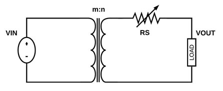
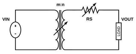
The SC DC-DC converter can be modelled as a transformer with an ideal conversion ratio and a series resistor, RS. SC DC-DC converters can be broadly classified into two types:

  • In a single topology switched capacitor DC-DC converter with one conversion ratio (Figure 1), the conversion ratio is chosen so that the maximum desired VOUT/VIN is achieved (with margin for losses including parasitic capacitance, gate drive losses etc.). For other smaller voltage conversion ratio requirements, the RS is increased (by frequency, duty cycle, etc.).
  • In a multiple topology switched capacitor DC-DC converter (Figure 2), the transformer ratio itself is modified by switching between topologies based on the required voltage conversion ratio.
Figure 1. Theoretical Model – Single Topology
Figure 2. Theoretical Model – Multiple Topology

Efficiency Comparison Between Single And Multiple Topology Converters

Single Topology Switched Capacitor DC-DC Converter

Each SC DC-DC converter topology has an ideal voltage conversion ratio (iVCR). This iVCR is the maximum ratio between the output voltage and the supply voltage of the conversion block. In practice, this iVCR is the upper bound for the actual VCR and the converter can only operate at a theoretical efficiency of 100% when this iVCR is met.

In SC DC-DC converters with a single conversion ratio of iVCR, the theoretical maximum efficiency that can be achieved is given by:

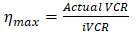
This means that for other conversion ratios required due to changes in supply and output programmability, the efficiency suffers.

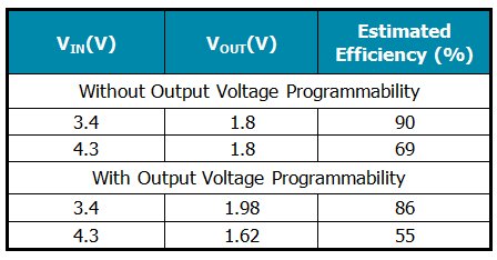
Table 1 shows estimated efficiencies of a 1.8 V nominal output single topology converter supplied by a battery with its voltage varying from 3.4 V to 4.3 V. The efficiency suffers about 20% as you move further away from iVCR towards smaller VCRs. This is worsened to about 30% in cases where the output voltage needs to be programmable as this introduces a wider range of VCRs to cover.

A 5/9 topology is chosen for the non-programmable converter and a 5/8 topology is chosen for the programmable converter in this application case.

Table 1. Efficiency of a single topology switched capacitor DC-DC converter

Multiple Topology Switched Capacitor DC-DC Converter

By switching between various topologies based on the required VCR, a multiple topology SC DC-DC converter maintains better efficiency over the full range of converter supply and output voltages.

The VCR at which to switch to a different topology can be pre-determined based on the estimated drop in efficiency below a desired minimum level. Having more topologies with closely spaced iVCRs achieves higher minimum efficiency of the SC DC-DC converter.

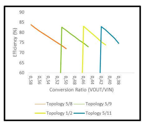
Table 2 shows estimated efficiencies for the 1.8 V output DC-DC converter using a 4-toplogy SC DC-DC converter. Figure 3 is the corresponding depiction of this architecture’s efficiency in graphical form.

Table 2. Efficiency of a multiple (4) topology switched capacitor DC-DC converter

Table 2. Efficiency of a multiple (4) topology switched capacitor DC-DC converter

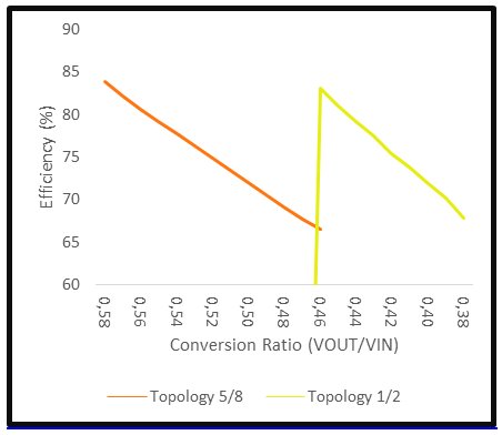
Figures 3 and 4 show the efficiency of the same system under a 4-topology and 2-topology SC DC-DC converter architecture. It is clear that quicker switching to a different iVCR topology as the required conversion ratio moves farther away from the ideal ratio for that topology helps in maintaining a higher minimum system efficiency.

This image has an empty alt attribute; its file name is 20201012e_3.jpg
Figure 3. Efficiency of 4-Topology Switched Capacitor DC-DC Converter
This image has an empty alt attribute; its file name is 20201012e_4.jpg
Figure 4. Efficiency of 2-Topology Switched Capacitor DC-DC Converter

Efficiency Tradeoffs

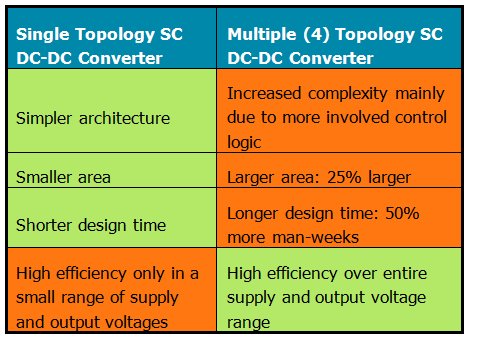
The tradeoffs to achieve this high SC DC-DC converter efficiency are the increased area due to additional switches needed for switching between multiple topologies and the control logic required to implement it. For this application case, Vidatronic estimates that the 4-toplogy SC DC-DC converter can be as much as 25% larger than a single topology SC DC-DC converter and required design resources will be about 50% higher.

Table 3. Tradeoff Summary

Summary

Since SC DC-DC converters are a great fit for the ever-broadening array of IoT fields where battery-operated devices dominate, it is necessary to understand the efficiency tradeoffs inherent in these converters. Based on the end application’s priorities, the customer can choose between single topology SC DC-DC converters and various multiple topology SC DC-DC converter architectures.

Related

Source: Vidatronic

Recent Posts

Image credit: Samtec

How to Match the Right Connector with Protocol Requirements

6.11.2025
2

Smoltek CNF-MIM Capacitors Pass 1,000h Reliability Test

6.11.2025
1

Capacitor Lead Times: October 2025

6.11.2025
2

Paumanok Unveils Aluminum Capacitor Foils World Markets Study 2025-2030

6.11.2025
1

Transformer Design Optimization for Power Electronics Applications

4.11.2025
10

Microhardness — the Hidden Key to Understanding MnOx Cathode Quality in Tantalum Capacitors

3.11.2025
17

Samsung to Invest in its Philippine MLCC Facility to Meet Automotive Demand

3.11.2025
16

Lightweight Model for MLCC Appearance Defect Detection

3.11.2025
19

DMASS Reports First Positive Signs of European Distribution Market in Q3/25

3.11.2025
7

TAIYO YUDEN Releases 22uF MLCC in 0402 Size for AI Servers

3.11.2025
14

Upcoming Events

Nov 4
November 4 @ 12:00 - November 6 @ 14:15 EST

Wirebond Materials, Processes, Reliability and Testing

Nov 6
14:30 - 16:00 CET

Self-healing polymer materials for the next generation of high-temperature power capacitors

Nov 11
17:00 - 18:00 CET

Industrial Applications Demand More from Interconnects in Next-Gen Designs

View Calendar

Popular Posts

  • Buck Converter Design and Calculation

    0 shares
    Share 0 Tweet 0
  • Boost Converter Design and Calculation

    0 shares
    Share 0 Tweet 0
  • LLC Resonant Converter Design and Calculation

    0 shares
    Share 0 Tweet 0
  • Flyback Converter Design and Calculation

    0 shares
    Share 0 Tweet 0
  • Ripple Current and its Effects on the Performance of Capacitors

    3 shares
    Share 3 Tweet 0
  • MLCC and Ceramic Capacitors

    0 shares
    Share 0 Tweet 0
  • Dual Active Bridge (DAB) Topology

    0 shares
    Share 0 Tweet 0
  • What is a Dielectric Constant and DF of Plastic Materials?

    4 shares
    Share 4 Tweet 0
  • SEPIC Converter Design and Calculation

    0 shares
    Share 0 Tweet 0
  • Flying Capacitors

    0 shares
    Share 0 Tweet 0

Newsletter Subscription


Passive Components Blog

© EPCI - Leading Passive Components Educational and Information Site

  • Home
  • Privacy Policy
  • EPCI Membership & Advertisement
  • About

No Result
View All Result
  • Home
  • Knowledge Blog
  • PCNS

© EPCI - Leading Passive Components Educational and Information Site

This website uses cookies. By continuing to use this website you are giving consent to cookies being used. Visit our Privacy and Cookie Policy.
Go to mobile version