


This article provides an overview of impact of shielding materials on shielding effectiveness. The post is based on Würth Elektronik‘s “Reference Guide ABC of Shielding” that can be ordered from WE website here. Published under permission by Würth Elektronik.
The shielding attenuation properties presented so far assume that the housing has no openings, gaps, or seams. However, it has been shown that for magnetic fields other than low frequency, almost any metal can achieve a shielding effectiveness of over 100 dB across the entire spectrum. This is because typical device housings have openings such as windows, vents, seams, and joints that degrade the shielding effectiveness of the conductive material.
For instance, the shielding effectiveness of an enclosure can be reduced to 40 dB or less due to loss of enclosure integrity caused by discontinuities. Typical discontinuities are:
- Cover plates for opening from the enclosure
- Holes or slots for cooling
- Power and signal cable glands
- Displays, instruments, and switches
- Seams between individual sheet metal components of the housing.
Therefore, the designer of a device must carefully weigh the shielding trade-offs and take various measures to minimize the effects on shielding integrity. While the influence of isolated discontinuities can be calculated in principle, the numerous influencing parameters make it almost impossible to perform a meaningful calculation of the overall structure. To address this challenge, the following section provides practical examples to illustrate the influencing parameters, enabling the designer to project effective measures from these examples into the product to be developed.
Openings in a Housing
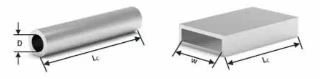
There are various methods for determining the shielding effectiveness of openings. The simplest assumption is that the attenuation is directly proportional to the ratio of the longest slot dimension d and the frequency. Consequently, Thus, with d = λ/2, or with 20 · log(λ/2d), the shielding effectiveness is zero. The shielding attenuation, therefore, increases linearly with decreasing frequency until it reaches the maximum determined by the shielding material. Correction factors can be considered for the aspect ratio of slot-shaped openings, the sheet thickness, and the so-called shadow effect. To comprehend these factors in the attenuation and, of course, in the radiation of an opening, it is beneficial to examine the formulas for the slot and the round opening. Figure 1. illustrates both openings and their corresponding geometric parameters.
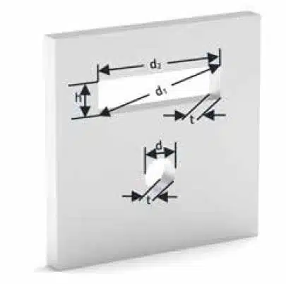
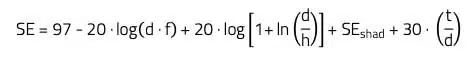
For a rectangular slot, as shown in Figure 1., the attenuation can be calculated as follows:
Where,
- SE: Shielding effectiveness in dB
- f: Signal frequency in MHz
- d, h: Slot length (d1 or d2) and height (mm); for further clarification, please refer to the note
- t: Depth of slot, usually thickness of material
- SEshad: Shadow effect (set default to 3 dB)
- ln: Natural logarithm
Note: Strictly speaking, the longest distance/diagonal in the opening is decisive, i.e., the length
d1. The narrower the opening, the smaller the difference between d1 and d2.
For a round opening, as shown in Figure 1., the damping can be calculated as follows:

Where,
- d: Diameter in mm
If the sheet is thin (t << d), in both formulas the last term becomes very small. This is the part of the formula that represents the absorption attenuation. SEshad is the shadow effect. It occurs when the slot is in the conductive wall of an otherwise closed enclosure, so it is a process that must be considered from an EMC point of view in the case of coupling fields through a gap into an enclosure.
The shadow effect, influenced by the slot’s size, housing dimensions, and frequency, creates field dispersion within the housing, leading to attenuation. In typical enclosures, the shadow effect contributes less than 5 dB, making 3 dB a suitable standard value for the equation. However, at low frequencies, the equation may yield values exceeding the SE of a solid panel, where the enclosure without the slot is the limit. It’s important to note that any opening, such as a small gap due to poor joint contact, should be considered a slot. At high frequencies or with long slots, if d ≥ λ/2, the attenuation of the slot or opening is 0 dB.
Additionally, factors like field type (E or H), distance between the opening and the field source, and polarization must be considered. To simplify the calculation, the shielding effective-ness is assumed under the “worst case” condition, disregarding correction factors. Consequently, SEshad and the absorption attenuation term for thick sheets are set to zero.
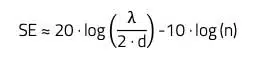
Simplified, the shielding effectiveness of an opening (rectangular or round) is thus given:
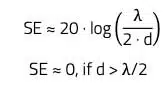
Where,
- d: Longest linear expansion of the opening in m
Experience shows that an opening should have a minimum attenuation of 20 dB.
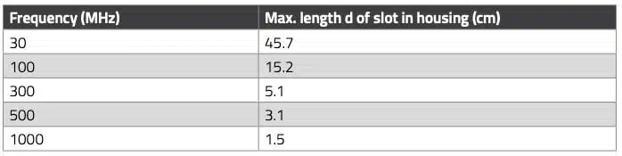
With SE approximately equal to 20 times the logarithm of the ratio of the length to the diameter of the slot, and l equal to 300 divided by the frequency (in meters and MHz, respectively), the maximum slot opening in the housing can be determined. The slot opening is calculated using the highest frequency occurring in the system. It’s important to note that, for instance, it’s not the clock frequency of the controller but the harmonics of the clock signal that should be considered. Table 1. provides some slot widths based on different frequencies.
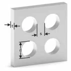
In the case of several openings, the shielding effectiveness for d > s and d >> t, where s is the maximum separation distance between openings, is calculated with the parameters according to Figure 2. as follows:
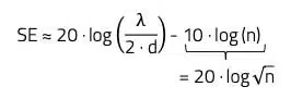
Furthermore, the following conditions apply:
- s: d: Maximum separation distance between openings in m; s < λ/2
- Longest linear expansion of the opening in m; d > λ/2
- n: Number of openings
The formula applies to both round and rectangular openings.
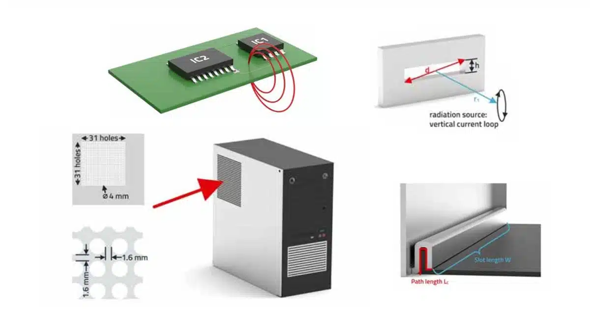
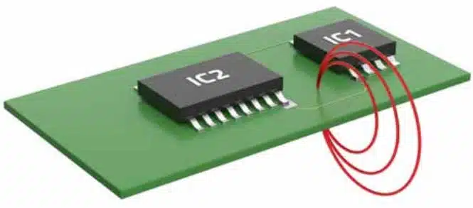
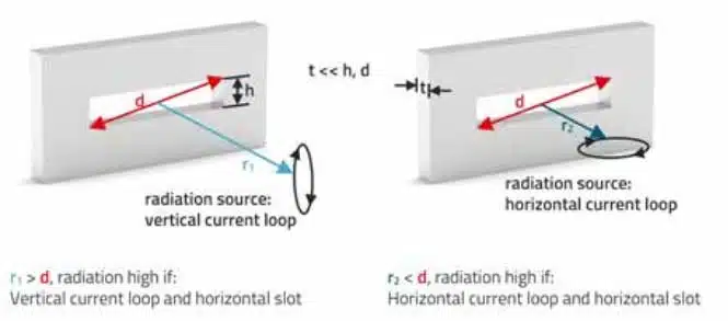
The polarization of the field source and its distance to the opening have a considerable influence on the shielding effectiveness. The most common cause of interference emission from an electronic assembly is a magnetic field generated by a current loop (differential mode interference), as shown in Figure 3.
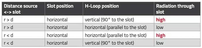
The magnetic interference field generated by the current loop inside the device can be radiated through a slot in the housing. Figure 4. with Table 2. shows an overview of the relationships between the conditions for radiating a magnetic field through a slot.
Wave Guide Effect
If the sheet depth exceeds a certain value, a wave guide effect occurs, which leads to field damping. Waveguides can only transmit signals above a certain frequency, the so-called cutoff frequency. The reason for this is that the waveguide must be able to “propagate” the signals, and this depends on the wavelength of the signal. Below the cutoff frequency, the signal is attenuated. Figure 5. shows schematically the geometric conditions for a waveguide.
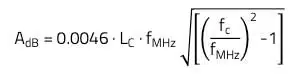
In the case of a rectangular slot, or round opening, the conditions for the attenuation are as follows:
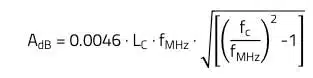
Where,
- AdB: Attenuation in dB
- LC: Opening depth, or thickness of the material in inch
- fMHz: Signal frequency in MHz
- fC: Cutoff frequency of the opening
- 5900/W for a rectangular opening
- 6920/D for a round opening
For fC >> fMHz there is a mathematical simplification with:

in the case of a rectangular opening.
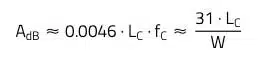
in the case of a round opening.
Practical Examples of Typical Apertures and Their Preventative Measures
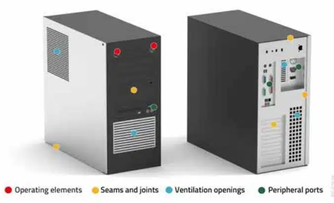
A typical tower computer, illustrated in Figure 6., serves as the basis for the practical example.
Ventilation Grid
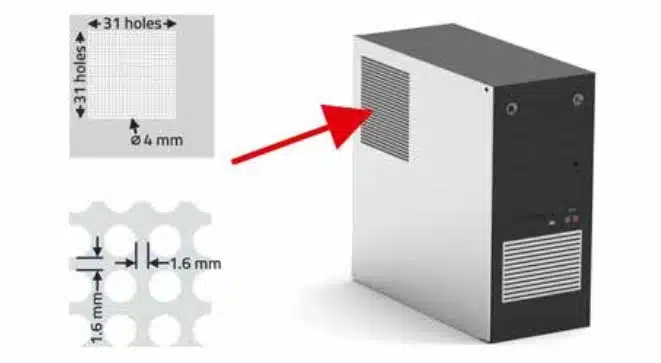
According to Figure 7., with d > s and d >> t, the shielding effectiveness is calculated as follows:
- Signal frequency f: 1 GHz (assumption)
- Opening diameter d: 4 mm
- Opening distance s: 1.6 mm
- Number of openings: 961
The total damping of the grille is also calculated:
So the result is:
f = 1 GHz ➔ λ = 30 cm
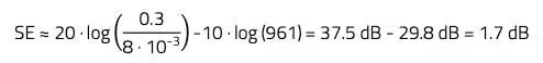
The shielding effectiveness of the perforated grid is only 1.7 dB at a frequency of 1 GHz. In practice, this value can lead to increased interference radiation on a computer board.
Contact Spring Gasket For Housing Cover
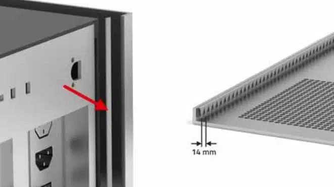
According to Figure 8. the shielding effectiveness is calculated as follows:
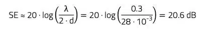
Where,
- λ: d: 30 cm (Signal frequency f = 1 GHz (assumption)
- Spring distance or slot length d = 14 mm
If we consider the shielding effectiveness of just one slot in the contact spring gasket, which is formed by the distance between two springs, it is 20.6 dB at a frequency of 1 GHz. This value proves to be completely sufficient in practice, but the high number of these slots in the sheet metal cover greatly reduces the overall shielding effectiveness of the enclosure.
Insert for Covering the Drive Slot
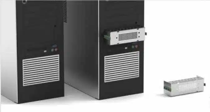
To prevent the radiation of radio interference generated by the PC’s internal electronics via the drive bay, a sheet metal insert was integrated into the bay. The sheet metal insert is in contact all around with embossed springs and has a round hole array at the front to allow air to be drawn out at the front, as shown in Figure 9.
Cable Bushing through Housing
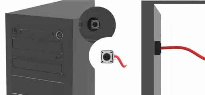
If the cable feeds of operating and display elements are brought out through an opening in the housing, the cable ends located outside with the operating elements often radiate radio interference that is coupled from the inside of the housing to the outside. To avoid this, as shown in Figure 10., the operating element, such as a switch, can be left in the housing. The switch is then actuated via a plastic dome. The light from LEDs can be fed to the outside via plastic light guides, so that here, too, cable routing from the inside of the device to the outside is not necessary.
Mounting of The Side Wall with Groove
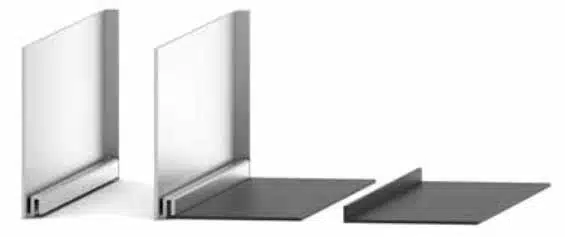
An additional groove in the housing cover allows contact on three levels. However, it cannot be determined at which point contact is made over the length of the groove. If additional contacts had been implemented over the length of the groove, the wave guide effect could be used for a defined length. The following is the calculation for an upper interference frequency limit of 1 GHz.
The calculation is done with:
Where,
- AdB: Attenuation in dB
- LC: Opening depth, or thickness of the material in inch (refer to Figure 1.21)
- fMHz: Signal frequency in MHz
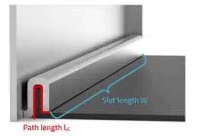
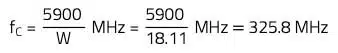
- fC: Cutoff frequency in MHz of the opening with a rectangular shape; fC = 5900/W and the geometry according to Figure 12.
Thus, according to Figure 12. with W = 46 cm (18.11 inch) and LC = 3 cm (1.18 inch) the following calculation results:
This means, that in order to set the cutoff frequency above 1 GHz, at least 2 additional contacts must be inserted to reduce the slot width to 1/3. With 9 additional contacts, the following attenuation results were obtained:
- W = 18.11 inch/10 = 1.8 inch
- LC = 1.18 inch
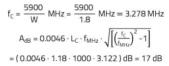
The attenuation of a slot is 17 dB at 1 GHz. Since there are 10 slots in series, the slot depth should be increased to get enough reserve.
Related articles:
- Electromagnetic Housing Shielding and Its Effectiveness
- Parameters of Shielding Attenuation
- Influence of Shielding Materials on Shielding Effectiveness


