Passive Components Blog
No Result
View All Result
  • Home
  • NewsFilter
    • All
    • Aerospace & Defence
    • Antenna
    • Applications
    • Automotive
    • Capacitors
    • Circuit Protection Devices
    • electro-mechanical news
    • Filters
    • Fuses
    • Inductors
    • Industrial
    • Integrated Passives
    • inter-connect news
    • Market & Supply Chain
    • Market Insights
    • Medical
    • Modelling and Simulation
    • New Materials & Supply
    • New Technologies
    • Non-linear Passives
    • Oscillators
    • Passive Sensors News
    • Resistors
    • RF & Microwave
    • Telecommunication
    • Weekly Digest

    Common Mistakes in Flyback Transformer Specs

    Vishay Releases Miniature SMD Trimmers for Harsh Environments

    Würth Elektronik Releases Push-Button and Main Switches

    Littelfuse Unveils High-Precision TMR Angle Magnetic Sensors

    Stackpole Extends Voltage of High Temp Chip Resistors

    High Voltage MLCCs Meeting the Growing Demand for Efficiency in Power Conversion

    Bourns Releases High Power High Ripple Chokes

    KYOCERA AVX Releases Hermaphroditic WTW and WTB Connectors

    Radiation Tolerance of Tantalum and Ceramic Capacitors

    Trending Tags

    • Ripple Current
    • RF
    • Leakage Current
    • Tantalum vs Ceramic
    • Snubber
    • Low ESR
    • Feedthrough
    • Derating
    • Dielectric Constant
    • New Products
    • Market Reports
  • VideoFilter
    • All
    • Antenna videos
    • Capacitor videos
    • Circuit Protection Video
    • Filter videos
    • Fuse videos
    • Inductor videos
    • Inter-Connect Video
    • Non-linear passives videos
    • Oscillator videos
    • Passive sensors videos
    • Resistor videos

    Percolation Phenomenon and Reliability of Molded Power Inductors in DC/DC converters

    Root Causes and Effects of DC Bias and AC in Ceramic Capacitors

    How to Calculate the Output Capacitor for a Switching Power Supply

    Switched Capacitor Converter Explained

    Understanding Inductor Dot Markings and Their Application in LTspice

    Accelerating Full Bridge LLC Resonant Converter Design with Frenetic AI

    Understanding Switched Capacitor Converters

    Coupled Inductors Circuit Model and Examples of its Applications

    Inductor Resonances and its Impact to EMI

    Trending Tags

    • Capacitors explained
    • Inductors explained
    • Resistors explained
    • Filters explained
    • Application Video Guidelines
    • EMC
    • New Products
    • Ripple Current
    • Simulation
    • Tantalum vs Ceramic
  • Knowledge Blog
  • Suppliers
    • Who is Who
  • Events
No Result
View All Result
Passive Components Blog
No Result
View All Result

Embedded Resistance Measurement

13.6.2017
Reading Time: 2 mins read
A A

source: EDN article

John Dunn -June 12, 2017.

RelatedPosts

Common Mistakes in Flyback Transformer Specs

Vishay Releases Miniature SMD Trimmers for Harsh Environments

Würth Elektronik Releases Push-Button and Main Switches

The EDN article provide some hints how to measure embedded resistive network.

Assume that you have a resistive tee network embedded in an impenetrable potting material and you want to make a direct measurement of the value of one of those resistors. Since you can’t access the center node, the other resistor(s) would seem to make that an impossible task, but it can be done.

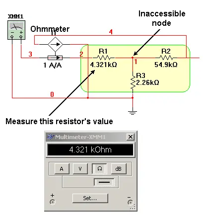
Figure 1: Embedded Resistance Measurement Problem

To measure the value of R1 in the above sketch, the nominal technique is to sense the current being delivered by the ohmmeter to R1 and to draw an equal value current out of R2 on the other side of the tee. The result will be zero current flowing in R3 and thus zero volts at the inaccessible node. This will make the ohmmeter think it’s seeing R1 alone.

<In an idealized SPICE simulation, the concept looks like the following.

Figure 2: Embedded Resistance Measurement Concept

From a practical standpoint, this concept can be implemented with a current-to-voltage converter and a Howland current pump. The sketch below shows virtual op-amps for the sake of illustrational clarity, but real world op-amps can be brought to bear too.

Figure 3: Embedded Resistance Measurement Implementation

In the above case, the ohmmeter injects 10 nA into R4. That same current is carried by R7 which yields an output from U1 of 100 µV. The Howland circuit places that 100 µV across R12 which results in 10 nA being drawn out of R5. With that current balance, the current through R6 is zero and so is the voltage across R6. The ohmmeter therefore registers the value of R4.

Related

Recent Posts

Vishay Releases Miniature SMD Trimmers for Harsh Environments

14.8.2025
7

Stackpole Extends Voltage of High Temp Chip Resistors

13.8.2025
9

Bourns Unveils High Reliability Compact Micro Encoders

5.8.2025
9

PCNS 2025 Final Program Announced!

4.8.2025
84

Bourns Released Rugged, High-Power TO-247 Thick Film Resistor

30.7.2025
18

Stackpole Unveils 1W High Power Density Current Sense Chip Resistor

24.7.2025
19

Vishay Releases Industrial-Grade 3/8 Square Single-Turn Cermet Trimmer

23.7.2025
8

Modelithics Library Expands with 120 New Models

22.7.2025
7

Bourns Unveils Smallest Automotive Grade Thick Film Resistors

14.7.2025
35

Bourns Releases SMD Chip High-Power Metal Strip Current Sense Resistors in 2010 Case

10.7.2025
18

Upcoming Events

Aug 27
17:00 - 18:00 CEST

Capacitor Assemblies for High-Power Circuit Designs

Sep 3
15:30 - 17:30 CEST

How to Choose Your Magnetic Supplier

Sep 22
September 22 @ 13:00 - September 25 @ 15:15 EDT

Pre Cap Visual Inspection per Mil-Std-883 (TM 2017)

Sep 30
September 30 @ 12:00 - October 2 @ 14:00 EDT

MIL-Std-883 TM 2010

Oct 17
12:00 - 14:00 EDT

External Visual Inspection per MIL-STD-883 TM 2009

View Calendar

Popular Posts

  • Buck Converter Design and Calculation

    0 shares
    Share 0 Tweet 0
  • Boost Converter Design and Calculation

    0 shares
    Share 0 Tweet 0
  • Flyback Converter Design and Calculation

    0 shares
    Share 0 Tweet 0
  • LLC Resonant Converter Design and Calculation

    0 shares
    Share 0 Tweet 0
  • What is a Dielectric Constant and DF of Plastic Materials?

    4 shares
    Share 4 Tweet 0
  • Ripple Current and its Effects on the Performance of Capacitors

    3 shares
    Share 3 Tweet 0
  • Dual Active Bridge (DAB) Topology Explained

    0 shares
    Share 0 Tweet 0
  • How to Design an Inductor

    0 shares
    Share 0 Tweet 0
  • MLCC Case Sizes Standards Explained

    0 shares
    Share 0 Tweet 0
  • MLCC and Ceramic Capacitors

    0 shares
    Share 0 Tweet 0

Newsletter Subscription


Passive Components Blog

© EPCI - Leading Passive Components Educational and Information Site

  • Home
  • Privacy Policy
  • EPCI Membership & Advertisement
  • About

No Result
View All Result
  • Home
  • Knowledge Blog
  • Premium Suppliers

© EPCI - Leading Passive Components Educational and Information Site

This website uses cookies. By continuing to use this website you are giving consent to cookies being used. Visit our Privacy and Cookie Policy.
Go to mobile version