Passive Components Blog
No Result
View All Result
  • Home
  • NewsFilter
    • All
    • Aerospace & Defence
    • Antenna
    • Applications
    • Automotive
    • Capacitors
    • Circuit Protection Devices
    • electro-mechanical news
    • Filters
    • Fuses
    • Inductors
    • Industrial
    • Integrated Passives
    • inter-connect news
    • Market & Supply Chain
    • Market Insights
    • Medical
    • Modelling and Simulation
    • New Materials & Supply
    • New Technologies
    • Non-linear Passives
    • Oscillators
    • Passive Sensors News
    • Resistors
    • RF & Microwave
    • Telecommunication
    • Weekly Digest

    Dr. Tomas Zednicek Vision for Europe 2025 Passive Electronics Market

    Littelfuse Releases Industry-First SMD Fuse with 1500A Interrupting Rating at 277V

    TDK Unveils Industry Highest Rated Current Multilayer Chip Beads

    Vishay Releases Automotive SMD Thick Film Power Resistor for Enhanced Protection Against Short Transient Pulses

    Exxelia Power Film Capacitors Support Critical Systems Across Various Industries

    H2-Assisted Thermal Treatment of Electrode Materials Increases Supercapacitors Energy Density

    Modelithics Releases Components Library v25.0 for Keysight 

    How to design a 60W Flyback Transformer

    Researchers Present Hybrid Supercapacitor Zn-Ion Microcapacitors

    Trending Tags

    • Ripple Current
    • RF
    • Leakage Current
    • Tantalum vs Ceramic
    • Snubber
    • Low ESR
    • Feedthrough
    • Derating
    • Dielectric Constant
    • New Products
    • Market Reports
  • VideoFilter
    • All
    • Antenna videos
    • Capacitor videos
    • Circuit Protection Video
    • Filter videos
    • Fuse videos
    • Inductor videos
    • Inter-Connect Video
    • Non-linear passives videos
    • Oscillator videos
    • Passive sensors videos
    • Resistor videos

    How to design a 60W Flyback Transformer

    Modeling and Simulation of Leakage Inductance

    Power Inductor Considerations for AI High Power Computing – Vishay Video

    Coupled Inductors in Multiphase Boost Converters

    VPG Demonstrates Precision Resistor in Cryogenic Conditions

    Comparison Testing of Chip Resistor Technologies Under High Vibration

    EMC Challenges for High Speed Signal Immunity and Low EMI

    MOSFET Gate Drive Resistors Power Losses

    Modified Magnetic Reluctance Equivalent Circuit and its Implications

    Trending Tags

    • Capacitors explained
    • Inductors explained
    • Resistors explained
    • Filters explained
    • Application Video Guidelines
    • EMC
    • New Products
    • Ripple Current
    • Simulation
    • Tantalum vs Ceramic
  • Knowledge Blog
  • Suppliers
    • Who is Who
  • Events
No Result
View All Result
Passive Components Blog
No Result
View All Result

ESA Solar Orbiter Pass Extreme EMC and Magnetic Field Stress Test

25.9.2019
Reading Time: 3 mins read
A A

Source: ESA news

An important stage in the development of ESA’s Solar Orbiter mission was successfully completed, when a series of tests to validate the electromagnetic compatibility and magnetic properties was carried out on the spacecraft’s flight model. The mission require extra ordinary EMC and magnetic field strength from all mechanical and electrical components on board including passive components.

RelatedPosts

Dr. Tomas Zednicek Vision for Europe 2025 Passive Electronics Market

Littelfuse Releases Industry-First SMD Fuse with 1500A Interrupting Rating at 277V

TDK Unveils Industry Highest Rated Current Multilayer Chip Beads

After shipment from prime contractor Airbus Defence and Space in Stevenage, UK, last year, the Solar Orbiter spacecraft has been undergoing a series of tests at the premises of IABG in Ottobrunn, Germany, testing its thermal and mechanical properties, the deployment of several elements, and most recently its electromagnetic compatibility (EMC) and magnetic behaviour.

The EMC testing took place in an anechoic chamber at IABG, where the spacecraft was isolated from external electromagnetic interference. The chamber walls are covered with thousands of pointy pyramids that fully absorb reflections of electromagnetic waves, muting also any sound echoes and creating an eerie silence. Performed between 8 and 22 May, these tests were needed to verify that the spacecraft’s electrical equipment will be fully electromagnetically compatible throughout all phases of the mission.

Electromagnetic compatibility is a key aspect of any space mission, because electrical and electronic equipment can be a source of electromagnetic emissions and/or sensitive to such emissions, so the compatibility between the various onboard emission sources and their susceptibilities needs to be verified before launch from the Cape Canaveral launch site in Florida, USA

Analysis of the test data showed that the spacecraft meets the EMC requirements with respect to interactions with the TT&C subsystems onboard and with external equipment during launch. Analysis of the EMC test for the RPW instrument yielded results that were consistent with prior expectation from unit level testing and analysis, but further characterisation will be necessary during in-flight and in-orbit commissioning.

While most spacecraft undergo only EMC testing, missions that involve measuring magnetic fields in space with exquisite accuracy – such as Solar Orbiter, which will measure the magnetic field of the solar wind with its Magnetometer (MAG) and with the SCM component of the RPW instrument, or magnetospheric plasma missions like ESA’s Cluster and Swarm – require an additional set of tests to fully characterise their magnetic properties.

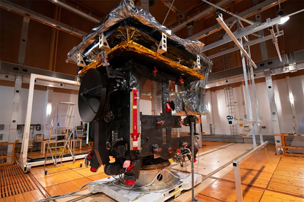
These tests were conducted in a unique facility, the magnetic field simulation facility (MFSA), located just outside the IABG premises in a nearby forest to avoid interference with human-generated magnetic fields. In addition to that, the facility consists completely of non-magnetic materials like wood, and contains twelve 15-m coils – nearly as large as the building – to create a homogeneous magnetic environment that compensates Earth’s own magnetic field, simulating outer space conditions.

The analysis of the magnetic tests indicates that the mission requirements were met within the limits of the testing facility. After launch, in the even quieter environment of space, further measurements during the commissioning phase will complement the results of these tests to fully characterise the magnetic properties of the spacecraft.

The spacecraft electromagnetic compatibility and magnetic cleanliness are especially important aspects for the science that Solar Orbiter will perform, not only for the RPW (EMC aspects) and MAG (magnetic properties) instruments. They are also key elements for the two particle detector instruments on board – the Solar Wind Plasma Analyser (SWA) and the Energetic Particles Detector (EPD) – in order to reconstruct the path of incoming particles that might be deflected by any residual spacecraft electric or magnetic field.


About Solar Orbiter

Solar Orbiter’s mission is to perform unprecedented close-up observations of the Sun. Its unique orbit will allow scientists to study the Sun and its corona in much more detail than previously possible, and to observe specific features for longer periods than can ever be reached by any spacecraft circling the Earth. In addition, Solar Orbiter will measure the solar wind close to the Sun, and provide high-resolution images of the uncharted polar regions of the Sun.

It will carry 10 state-of-the-art instruments. Remote sensing payloads will perform high-resolution imaging of the Sun’s atmosphere – the corona – as well as the solar disk. Other instruments will measure the solar wind and the solar magnetic fields in the vicinity of the orbiter. This will give us unprecedented insight into how our parent star works, and how we can better predict periods of stormy space weather, which are related to coronal mass ejections (CMEs) that the Sun throws our way from time to time.

Scheduled for launch in February 2020, Solar Orbiter will take just under two years to reach its initial operational orbit, taking advantage of gravity-assist flybys of Earth and Venus, and will subsequently enter a highly elliptical orbit around the Sun.

Solar Orbiter is an ESA-led mission with strong NASA participation.


featured image: Solar Orbiter in the magnetic field simulation facility. Credit: ESA–S. Corvaja


Related

Recent Posts

Vishay Releases Automotive SMD Thick Film Power Resistor for Enhanced Protection Against Short Transient Pulses

14.5.2025
1

Exxelia Power Film Capacitors Support Critical Systems Across Various Industries

13.5.2025
17

Modelithics Releases Components Library v25.0 for Keysight 

12.5.2025
14

How to design a 60W Flyback Transformer

12.5.2025
18

Murata Releases 008004 High-Frequency SMD Chip Inductor

12.5.2025
18

Fischer Releases High Vibration Robust Ratchet Locking USB-C Connector System

9.5.2025
5

KYOCERA AVX Releases Compact High-Directivity Couplers

7.5.2025
23

Tariffs Crush Sales Sentiment in April 2025 ECST Results

5.5.2025
74

High-Density PCB Assemblies For Space Applications

2.5.2025
13

Solid State Polymer Multilayer Capacitors For High Temperature Application

2.5.2025
45

Upcoming Events

May 28
16:00 - 17:00 CEST

Power Over Data Line

View Calendar

Popular Posts

  • Buck Converter Design and Calculation

    0 shares
    Share 0 Tweet 0
  • Boost Converter Design and Calculation

    0 shares
    Share 0 Tweet 0
  • What is a Dielectric Constant and DF of Plastic Materials?

    4 shares
    Share 4 Tweet 0
  • Flyback Converter Design and Calculation

    0 shares
    Share 0 Tweet 0
  • Dual Active Bridge (DAB) Topology Explained

    0 shares
    Share 0 Tweet 0
  • Coefficient of Linear Thermal Expansion on Polymers Explained

    0 shares
    Share 0 Tweet 0
  • Ripple Current and its Effects on the Performance of Capacitors

    3 shares
    Share 3 Tweet 0
  • LLC Resonant Converter Design and Calculation

    0 shares
    Share 0 Tweet 0
  • How to Design an Inductor

    0 shares
    Share 0 Tweet 0
  • MLCC Case Sizes Standards Explained

    0 shares
    Share 0 Tweet 0

Newsletter Subscription


Passive Components Blog

© EPCI - Leading Passive Components Educational and Information Site

  • Home
  • Privacy Policy
  • EPCI Membership & Advertisement
  • About

No Result
View All Result
  • Home
  • Knowledge Blog
  • Premium Suppliers

© EPCI - Leading Passive Components Educational and Information Site

This website uses cookies. By continuing to use this website you are giving consent to cookies being used. Visit our Privacy and Cookie Policy.
Go to mobile version