


Custom designed inductive components are widely used in the design of power conditioning equipment to individualize the conversion of energies for specific purposes. These components can be approved for application by individual qualification campaign either as a one off based on various international standards, as a qualified entry to the Qualified Parts List (QPL) or as a component designed, manufactured, and tested by a manufacturer registered on the Qualified Manufacturer List (QML) approved by Technology Flow Qualification (TFQ). Each solution is viable but presents different responsibilities and impacts on the manufacturer as well as on the buying entity.
The paper was presented by Lars A. Gregersen Flux A/S, Denmark at the 3rd PCNS 7-10th September 2021, Milano, Italy as paper No.1.1.
TECHNOLOGY FLOW QUALIFICATION
Background
Since introduction to the space industry in 1995, Flux (henceforth the manufacturer) has supplied custom designed inductive components based on a set of generic documentation tailored from MIL-STD-981 (design), MIL-PRF-27 (performance) and MIL-STD-202 (test). The setup entails periodic qualification campaigns in cooperation between manufacturer and buyers, batch verification tests and a time-consuming Parts Approval Document (PAD) review for end customer approval.
Technology Flow Qualification
The philosophy behind TFQ is to approve a manufacturer rather than approve an individual product or product series. The TFQ not only entails testing and approval of concept designs but can be seen as a super structure to an existing ISO9001 or AS9001 Quality Management System (QMS) establishing systematic routines involving operations such as sales, design, manufacturing, testing and every support function involved.
While preparing for QML status by TFQ, Flux and the ESCC developed the ESCC Detail Specification No. 3201/013 “Customized Magnetics (Inductors and Transformers) based on type FT. Based on 25 years heritage in space flight, the ESCC3201/013 documents the envelope of custom designing inductive components by function, materials, physical characteristics, maximum ratings, testing requirements and relations to ESCC Basic Specification 3201.
While the ESCC3201/013 documents the domain’s envelope of custom designing, an individual ESCC Magnetic Sheet describes the details of each custom designed product. The products are overall documented by ESCC3201/013 and the ESCC Magnetic Sheet in conjunction.
All documents and procedures are developed in accordance with ESCC Basic Specification No. 25400 “Requirements for the Technology Flow Qualification of Electronic Components for Space Application” including the manufacturers responsibility to report any relevant non-conformance and involving the ESCC in the process of determining appropriate actions for recovery, improvement, and prevention of incidents. The manufacturer submits an annual report to the ESCC containing a summary of all QMS and TRB relevant information and performs a biannual ESCC Qualification campaign consisting of products representative of the agreed ESCC Domain. The ESCC performs regular onsite audits of the manufacturers qualified facilities.
Production of product
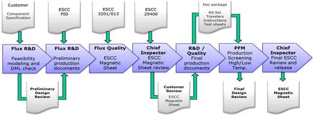
Whether a custom design is proposed by the engineers affiliated with the buying entity or the manufacturer is contracted to perform the design from performance requirements, an electronic modelling in a design program constructed to apply applicable rules of ESCC3201, utilizing approved materials from the manufacturers Declared Materials List (DML) and enabling manufacturing by processes of the Declared Process List (DPL) is performed. Review of the modelling ensure that required characteristics of the design are present and the design is producible.
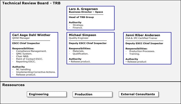
After engineering each design is reviewed by the appointed ESCC Chief Inspector and finally approved for release by the established ESCC Technical Review Board (TRB) consisting of an Executive Manager, the ESCC Chief Inspector and two Deputy Chief Inspectors with authority within engineering, quality, and manufacturing processes. The TRB is granted unlimited internal and external resources to confirm correlation between product and the manufacturers Process Identification Document (PID) known as ESCC Domain, as well as investigate and establish actions related to any suspected deviation. A deviation could be a new material requiring specific tests performed for inclusion on the DML or a variation of a manufacturing process requiring demonstration, vehicle test and documentation for adoption in manufacturing instructions, part documentation or QMS procedures. Furthermore, the ESCC has a permanent seat on the TRB and can participate at any meeting by choice.
An ESCC Magnetic Sheet can be reviewed and approved for release on the baseline of two scenarios:
- Prior manufacture and test of products with heritage
- Manufacture and test of one or more Proto Flight Models (PFM), applicable for new design variations
The procedure shall enforce the guarantee of successful manufacturing, test, and delivery of the ESCC Qualified product supplied to the buying entity. The approval process has many relations and can be illustrated as below:
CHALLENGES
Challenges encountered
The easy part of changing from the tailored MIL-STD-981 production to ESCC Qualified production has been the actual component manufacturing. As the approval is based on heritage the primary differences between the two production forms lie in the testing of products.
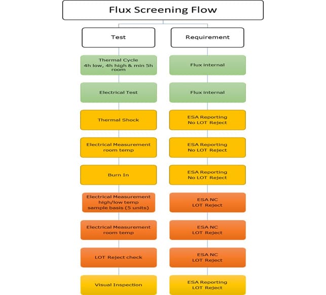
A Key Inspection Point (KIP) has been introduced between physical manufacturing and formal Screening. At this KIP, the components are electrically tested and visually inspected. The production travelers are inspected for their correctness in application and record. The full package is inspected against the prepared ESCC Magnetic Sheet ensuring full compliance. Passing KIP approve the components for formal Screen testing during which the manufacturer has a reporting duty towards the ESCC should any anomaly be detected. The products are subject to ESCC LOT Rejection criteria should any deviation be observed during electrical testing with a 5% threshold.
Finalizing the Screen Test, the parts and documentation are once more subjected to a Mandatory Inspection Point (MIP) for final visual inspection and documentation approval. Hereafter the production is released to Quality for production of ESCC Certificate of Conformity.
Both KIP and MIP are performed by dedicated and ESA Certified Inspectors.
Provided the preparation of design, manufacturing documentation and test documentation has been thorough and correct, the actual production and screen testing will not present any surprises.
This said, the biggest challenges have proved themselves in the process of preparing the documentation.
To convert a client-based design to an ESCC Qualified Parts involves an electronic feasibility modeling of the design. This model generator is linked to an electronic version of the Declared Material List (DML) containing a registry of mechanical tolerances, electrical parameters of conductors and the formulas to ensure ESCC derating rules in accordance with ESCC-Q-ST-30-11.
As the manufacturer has an obligation to always manufacture and test a product in full compliance with ESCC3201/013 Detail Specification and the product specific ESCC Magnetic Sheet, calculations may prove to be more conservative than requested by the client designer.
In some cases, in example High Low Temperature Test, predicting the exact result may be difficult, why the manufacturer may enter TBD in the first production test sheets. Based on actual testing the ESCC Magnetic Sheet will be updated to contain test proven parameters. In other cases, we have experienced differences in calculation of DCR and inductance, which is particularly tricky on toroid constructions featuring multiple layers of wire. In such instances, due to the obligation to always comply with the ESCC Magnetic Sheet, the manufacturer must be very insistent on introducing achievable data in the documentation. Differences often derive from a deviating view on tolerances. Some designers solely use the percentual core material tolerance as the total tolerance of the final product, whereas the manufacturer may add tolerances based on manufacturing experience. Tolerances can arise from the tension applied during winding, application of insulation layers or the use of impregnation fluids under vacuum or fluids displaying shrinking during curing.
While working actively with client designers a common understanding and formal agreement on parameters is achieved and the product can be approved for ESCC manufacturing with success.
During the manufacturers first operational year as QML by TFQ more than 100 designs have been converted and documented for ESCC Qualified manufacturing. More than 3.000 ESCC Qualified Parts have been delivered to projects.
SUMMARY & CONCLUSIONS
Gains of ESCC Qualified Parts,
Resulting from the described process of defining ESCC Qualified Parts, the buying entity can expect to always receive conforming products from the manufacturer. As such these products are qualified for use by ESA.
Without engaging in financial calculations, the following advantages of ESCC Qualified Parts in comparison to MIL-STD-981 Class B or Class S components can be highlighted:
- Best practices of heritage manufacturing and testing adopted into the ESCC3201/013.
- Parts are prequalified via the manufacturers ESCC Domain maintenance requiring bi-annual qualification test performed by the manufacturer towards ESCC.
- Product Assurance facilitated by the ESCC Chief Inspector and the ESCC TRB.
- Simplified approval process related to Parts Approval Document (PAD).
- Parts do not require testing, destructive or otherwise, by the buying entity upon delivery (no extra test vehicles).
- Power Burn In and X-Ray inspection is not required by ESCC3201 (optionally available).
- Batch level acceptance test is not required on productions from ESCC Qualified Manufacturer.
- Facility audited by ESCC.
This article is shortened version of original paper available at the link below or pdf download.


