Passive Components Blog
No Result
View All Result
  • Home
  • NewsFilter
    • All
    • Aerospace & Defence
    • Antenna
    • Applications
    • Automotive
    • Capacitors
    • Circuit Protection Devices
    • electro-mechanical news
    • Filters
    • Fuses
    • Inductors
    • Industrial
    • Integrated Passives
    • inter-connect news
    • Market & Supply Chain
    • Market Insights
    • Medical
    • Modelling and Simulation
    • New Materials & Supply
    • New Technologies
    • Non-linear Passives
    • Oscillators
    • Passive Sensors News
    • Resistors
    • RF & Microwave
    • Telecommunication
    • Weekly Digest

    YAGEO Releases Compact Coupled Inductors for High-Density VR Designs

    Enhancing Energy Density in Nanocomposite Dielectric Capacitors

    Advances in the Environmental Performance of Polymer Capacitors

    Vishay Releases DLA Tantalum Polymer Capacitors for Military and Aerospace

    Vishay Expanded Inductor Portfolio With More Than 2000 Stock Items 

    Paumanok Releases Capacitor Foils Market Report 2025-2030

    Modelithics Welcomes CapV as a Sponsoring MVP

    Wk 40 Electronics Supply Chain Digest

    Benefits of Tantalum Powder Stress–Strain Curve Evaluation vs Conventional Wet Test

    Trending Tags

    • Ripple Current
    • RF
    • Leakage Current
    • Tantalum vs Ceramic
    • Snubber
    • Low ESR
    • Feedthrough
    • Derating
    • Dielectric Constant
    • New Products
    • Market Reports
  • VideoFilter
    • All
    • Antenna videos
    • Capacitor videos
    • Circuit Protection Video
    • Filter videos
    • Fuse videos
    • Inductor videos
    • Inter-Connect Video
    • Non-linear passives videos
    • Oscillator videos
    • Passive sensors videos
    • Resistor videos

    Connector PCB Design Challenges

    Efficient Power Converters: Duty Cycle vs Conduction Losses

    Ripple Steering in Coupled Inductors: SEPIC Case

    SEPIC Converter with Coupled and Uncoupled Inductors

    Coupled Inductors in SEPIC versus Flyback Converters

    Non-Linear MLCC Class II Capacitor Measurements Challenges

    Percolation Phenomenon and Reliability of Molded Power Inductors in DC/DC converters

    Root Causes and Effects of DC Bias and AC in Ceramic Capacitors

    How to Calculate the Output Capacitor for a Switching Power Supply

    Trending Tags

    • Capacitors explained
    • Inductors explained
    • Resistors explained
    • Filters explained
    • Application Video Guidelines
    • EMC
    • New Products
    • Ripple Current
    • Simulation
    • Tantalum vs Ceramic
  • Knowledge Blog
  • Suppliers
    • Who is Who
  • Events
No Result
View All Result
Passive Components Blog
No Result
View All Result

Filter Poles and Zeros Explained

10.10.2023
Reading Time: 5 mins read
A A

This blog article from Knowles Precision Devices explains filter poles and zeros. In this article we go in-depth on the background information of how poles and zeros impact a transfer function to show how this information can be used to improve filter’s performance.

n previous article Filter Q Factor Explained we discussed the different ways you can look at Q factor, one of which is to consider the Pole Q factor (often used with more complex systems).

RelatedPosts

Knowles Releases High Q Non-Magnetic X7R MLCCs for Medical Imaging

Knowles Unveils High-Performance Safety-Certified MLCC Capacitors

Knowles Releases Inductors for Mission-Critical RF Applications

We also explained in that post that filters have a transfer function H(s) which tells us what an output signal will look like for a given input signal. Note that filter transfer functions are expressed in terms of the complex variable ‘s’. 

Poles and zeros are properties of the transfer function, and in general, solutions that make the function tend to zero are called, well, zeros, and the roots that make the function tend towards its maximum function are called poles.

Let’s look at how this works using a simple RC first order lowpass filter, like the one we looked at Basic Filter Circuits Explained (Figure 1).

Figure 1. A diagram of an RC first order low-pass filter.

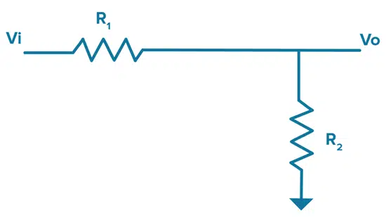
The transfer function for this filter written in terms of the complex frequency s, is as follows:

Thus, when s (frequency) = 0, the transfer function is 1 and we say the filter has a DC gain of 1. At s = -1/RC the transfer function will tend to infinity, so we say we have a single ‘pole’ at frequency s = -1/RC. 

Now, knowing there is a ‘pole’ at s = -1/RC really does not help us understand how the filter performs versus frequency ω, not yet anyway. To determine this, we are going to look at a more general transfer function for a first order filter:

Then to understand the frequency response we replace s with jω, where j is the imaginary number “i“:

Figure 2. A plot of the pole at in the complex plane of the ‘pole zero’ plot.

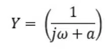
When jω = -a the transfer function tends to infinity, and we say we have a pole.

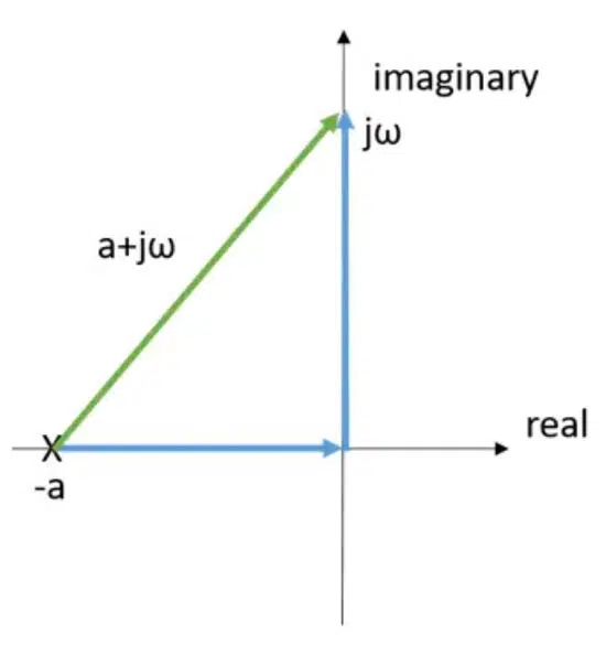
Next, if we plot the pole at -a in the complex plane of the ‘pole zero’ plot and mark it with an X, you get the graph shown in Figure 2. To see how the transfer function behaves at different values for frequency we can move the frequency value up and down the imaginary (vertical) axis for different values of jω see Figure 2.

Our transfer function will perform in the following manner – as the distance from the pole at to the frequency we are interested in grows, the signal will decrease since we are dividing by the size of that green vector (a+jω). Some additional general notes about this transfer function: 

  • at jω = 0 – We are as close to the pole as we can get if we stay on the imaginary axis and our transfer function Y will be at a maximum.
  • at jω = ∞ – We are as far away from the pole as we can get, and our transfer function Y will be at a minimum.
  • at jω = a – Our amplitude will be down by a ratio of √2 compared to its maximum, so in dB this is -3dB and we can say that is our cutoff frequency.

Therefore, in this simple case, our pole at -a gave us a cutoff frequency at a.

Similarly, our RC filter above with a pole at -1/RC gives us a cutoff frequency of ω = 1/RC.

This makes sense and we probably already know this is the cutoff frequency of an RC filter, but getting there via a roundabout route through a pole zero plot can help us understand how poles impact filter behavior. 

Using Pole and Zero Information to Enhance Your Filter Designs

Through this single pole example, we can make the following general observation about poles:

  • The closer your frequency of interest puts you on the complex plane relative to a pole, the filter’s transfer function will increase
  • The further you are away from a pole and the filter’s transfer function will decrease
  • Zeros have the opposite effect – the closer your frequency puts you to a pole, the filter transfer function will decrease and vice-versa.

As an RF designer, if you have an in-depth understanding of how poles and zeros work, you can take advantage of this information in your filter designs and improve your filter’s response. For example, you can place zeros near frequencies you want to reject and poles near frequencies you want to pass. 

Related

Source: Knowles Precision Devices

Recent Posts

Enhancing Energy Density in Nanocomposite Dielectric Capacitors

9.10.2025
6

Advances in the Environmental Performance of Polymer Capacitors

8.10.2025
16

Benefits of Tantalum Powder Stress–Strain Curve Evaluation vs Conventional Wet Test

3.10.2025
20

Electrolyte Selection and Performance in Supercapacitors

3.10.2025
17

Connector PCB Design Challenges

3.10.2025
21

Researchers Demonstrated High Energy Ceramic Capacitors Stable in Wide Temperature Range

2.10.2025
24

How to Manage Supercapacitors Leakage Current and Self Discharge 

1.10.2025
42

Experimental Evaluation of Wear Failures in SMD Inductors

1.10.2025
40

Resonant Capacitors in High-Power Resonant Circuits

1.10.2025
40
a Schematic diagram of the BNT-based components constructed based on the entropy-increase strategy. b Digital photograph, cross-sectional SEM image, and EDS mappings of the MLCCs. c Unipolar P-E loops of MLCCs as a function of applied E. d Wrec and η of the MLCCs as a function of applied E. The comparison of (e) Wrec and η, (f) η and UF of the MLCCs with those of other recently reported state-of-the-art MLCCs. source: Nature Communications

Researchers Proposed Enhanced Energy Storage MLCC

1.10.2025
19

Upcoming Events

Oct 14
16:00 - 17:00 CEST

Smart Sensors, Smarter AI: Building Reliable Edge Systems

Oct 17
12:00 - 14:00 EDT

External Visual Inspection per MIL-STD-883 TM 2009

Oct 20
October 20 - October 23

Digital WE Days 2025 – Virtual Conference

Oct 21
October 21 @ 12:00 - October 23 @ 14:15 EDT

Space and Military Standards for Hybrids and RF Microwave Modules

Oct 28
8:00 - 15:00 CET

Power Up Your Design: SN6507 and the Ready-to-Use Development Kit

View Calendar

Popular Posts

  • Buck Converter Design and Calculation

    0 shares
    Share 0 Tweet 0
  • Boost Converter Design and Calculation

    0 shares
    Share 0 Tweet 0
  • Flyback Converter Design and Calculation

    0 shares
    Share 0 Tweet 0
  • LLC Resonant Converter Design and Calculation

    0 shares
    Share 0 Tweet 0
  • What is a Dielectric Constant and DF of Plastic Materials?

    4 shares
    Share 4 Tweet 0
  • SEPIC Converter Design and Calculation

    0 shares
    Share 0 Tweet 0
  • Dual Active Bridge (DAB) Topology Explained

    0 shares
    Share 0 Tweet 0
  • Ripple Current and its Effects on the Performance of Capacitors

    3 shares
    Share 3 Tweet 0
  • MLCC and Ceramic Capacitors

    0 shares
    Share 0 Tweet 0
  • Flying Capacitors Explained

    0 shares
    Share 0 Tweet 0

Newsletter Subscription


Passive Components Blog

© EPCI - Leading Passive Components Educational and Information Site

  • Home
  • Privacy Policy
  • EPCI Membership & Advertisement
  • About

No Result
View All Result
  • Home
  • Knowledge Blog
  • Premium Suppliers

© EPCI - Leading Passive Components Educational and Information Site

This website uses cookies. By continuing to use this website you are giving consent to cookies being used. Visit our Privacy and Cookie Policy.
Go to mobile version