Passive Components Blog
No Result
View All Result
  • Home
  • NewsFilter
    • All
    • Aerospace & Defence
    • Antenna
    • Applications
    • Automotive
    • Capacitors
    • Circuit Protection Devices
    • electro-mechanical news
    • Filters
    • Fuses
    • Inductors
    • Industrial
    • Integrated Passives
    • inter-connect news
    • Market & Supply Chain
    • Market Insights
    • Medical
    • Modelling and Simulation
    • New Materials & Supply
    • New Technologies
    • Non-linear Passives
    • Oscillators
    • Passive Sensors News
    • Resistors
    • RF & Microwave
    • Telecommunication
    • Weekly Digest

    Benefits of Tantalum Powder Stress–Strain Curve Evaluation vs Conventional Wet Test

    Electrolyte Selection and Performance in Supercapacitors

    Connector PCB Design Challenges

    Researchers Demonstrated High Energy Ceramic Capacitors Stable in Wide Temperature Range

    Stackpole Offers High Voltage Plate Resistors up to 40KV

    How to Manage Supercapacitors Leakage Current and Self Discharge 

    Qualification of Commercial Supercapacitors for Space Applications

    Experimental Evaluation of Wear Failures in SMD Inductors

    Resonant Capacitors in High-Power Resonant Circuits

    Trending Tags

    • Ripple Current
    • RF
    • Leakage Current
    • Tantalum vs Ceramic
    • Snubber
    • Low ESR
    • Feedthrough
    • Derating
    • Dielectric Constant
    • New Products
    • Market Reports
  • VideoFilter
    • All
    • Antenna videos
    • Capacitor videos
    • Circuit Protection Video
    • Filter videos
    • Fuse videos
    • Inductor videos
    • Inter-Connect Video
    • Non-linear passives videos
    • Oscillator videos
    • Passive sensors videos
    • Resistor videos

    Connector PCB Design Challenges

    Efficient Power Converters: Duty Cycle vs Conduction Losses

    Ripple Steering in Coupled Inductors: SEPIC Case

    SEPIC Converter with Coupled and Uncoupled Inductors

    Coupled Inductors in SEPIC versus Flyback Converters

    Non-Linear MLCC Class II Capacitor Measurements Challenges

    Percolation Phenomenon and Reliability of Molded Power Inductors in DC/DC converters

    Root Causes and Effects of DC Bias and AC in Ceramic Capacitors

    How to Calculate the Output Capacitor for a Switching Power Supply

    Trending Tags

    • Capacitors explained
    • Inductors explained
    • Resistors explained
    • Filters explained
    • Application Video Guidelines
    • EMC
    • New Products
    • Ripple Current
    • Simulation
    • Tantalum vs Ceramic
  • Knowledge Blog
  • Suppliers
    • Who is Who
  • Events
No Result
View All Result
Passive Components Blog
No Result
View All Result

Fluorescence Microscopy + dye penetrant test on EEE Parts

1.10.2018
Reading Time: 4 mins read
A A

Source: Alter Technology article

by Francisco Javier Aparicio Rebollo
The Fluorescence Microscopy + dye penetrant test is a technique that combines two inspection methods commonly used for the detection of surface anomalies such as cracks, porosity, laps, delaminations, and other discontinuities.

RelatedPosts

Benefits of Tantalum Powder Stress–Strain Curve Evaluation vs Conventional Wet Test

Electrolyte Selection and Performance in Supercapacitors

Connector PCB Design Challenges

This joint approach is intended to highlight and resolve surface anomalies thanks to the irreversible infiltration with a fluorescent marker. Hence, fluorescent-based inspection methods are mandatory or highly recommended by different international regulations and reference books for space materials in the case of non-porous surfaces: ASTM international (ASTM E1417), MIL-STD standards MIL-STD-750 and MIL-STD-833 (USA Defense and Logistics Agency) and “Materials and Processes for Spacecraft and High Reliability Applications” (Barrie Dunn, Springer 2015).

Other characteristics of the technique are:

  • Non-destructive character.
  • Cost effective.
  • Requires sample preparation.
  • Higher sensitivity than conventional optical-microscopy methods.

Practical examples.
Main advantages of the technique lie on the dual specificity of the fluorescence phenomena which is exclusively activated under specific illumination wavelength (excitation light colour) and provides wavelength-specific light emission (specific emission colour). This allows us to unambiguously identify surface anomalies difficult to be resolved by naked-eye inspection. Due to the simplicity, the non-destructive character and the high sensitivity both conventional dye penetration test and the fluorescent microscopy dye-penetration test are commonly used not only in the space and aerospace sectors but also in other fields requiring of completely crack free materials such as oil and gas industry and power generation.

In Alter Technology dye penetrant testes are routinely used to verify the hermeticity of EEE parts by visual fluorescence inspection.

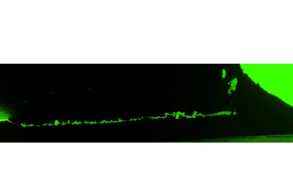
To improve the quality of our inspections processes they are also included within the verification protocol of high reliability surface mounted devices and other PCB systems. The figure shows one representative example of the latter application. Pictures at the left correspond to the cross-section of a soldered SMD leaded-device. In the figure on the top it is evident the presence of a crack at the solder however this optical image does not reveal the actual crack length. In this case fluorescence microscopy is used to disclose how the crack extend along the solder lead interface and determine the length of the crack which is a critical rejection/acceptance criteria.

Optical Image

Fluorescence MicroscopyFluorescence Microscopy

Fluorescence microscopy after dye infiltration

Fluorescence Microscopy


As an additional advantage related to this example, since dye infiltration is conducted before microsection only those crack present before cutting are outlined. Therefore, fluorescent inspection allows us to discard other features that eventually might be produced during microsection. This and other characterises makes it a valuable tool for failure analyses. In other application (picture beside) the technique is used to analyse wire separation in crimped connectors.


Figure: Wire separation in crimped connectors


Due to the fluorescent mechanism (see next section) proper fluorescence inspection requires the suitable selection of the fluorescent tag and the optical systems adapted to the fluorescence characteristics of the fluorophore (excitation lamps, fluorescence filters, and others). With this concerns Alter Technology team consist of experienced researchers in materials science and fluorescence techniques.Fluorescence Microscopy

How it works

Fluorescence is the emission of light observed when some chemical elements (rare earths) organic compounds (organics dyes) and other confined materials (Quantum dots) are irradiated, typically with short-wavelength (UV) light. Taking as example an organic fluorophore, fluorescence emission is excited when a photon is absorbed by substance. Subsequent to this excitation process the fluorophore is promoted to a high electronic level as illustrated by the Jablosnki diagram (picture beside). In the excited state the molecule undergoes very fast non-emitting dissipation processes and transition toward the lower sub-vibration level of the exited state. In fluorescent compounds, the remaining excess of energy is released in form of light at wavelengths characteristic the used fluorophore. In general, fluorescence emission the is less energetic (longer wavelength) that the excitation beam as consequences of the previously mentioned excited-state dissipation processes. The wavelength difference between the excitation and emission wavelength is denominated stokes shift. This is an important factor for the de selection of the suitable fluorophore depending on the intending application. For marking proposes large stokes shift is very recommended to filter out the reflection of the excitation beam from the emission signal.


Featured image: crack extending along the base on a SMD device, image credit: Alter Technology

Related

Recent Posts

Benefits of Tantalum Powder Stress–Strain Curve Evaluation vs Conventional Wet Test

3.10.2025
7

Electrolyte Selection and Performance in Supercapacitors

3.10.2025
3

Connector PCB Design Challenges

3.10.2025
12

Researchers Demonstrated High Energy Ceramic Capacitors Stable in Wide Temperature Range

2.10.2025
15

Stackpole Offers High Voltage Plate Resistors up to 40KV

2.10.2025
12

How to Manage Supercapacitors Leakage Current and Self Discharge 

1.10.2025
20

Qualification of Commercial Supercapacitors for Space Applications

1.10.2025
25

Experimental Evaluation of Wear Failures in SMD Inductors

1.10.2025
24

Resonant Capacitors in High-Power Resonant Circuits

1.10.2025
21
a Schematic diagram of the BNT-based components constructed based on the entropy-increase strategy. b Digital photograph, cross-sectional SEM image, and EDS mappings of the MLCCs. c Unipolar P-E loops of MLCCs as a function of applied E. d Wrec and η of the MLCCs as a function of applied E. The comparison of (e) Wrec and η, (f) η and UF of the MLCCs with those of other recently reported state-of-the-art MLCCs. source: Nature Communications

Researchers Proposed Enhanced Energy Storage MLCC

1.10.2025
13

Upcoming Events

Oct 8
11:00 - 12:00 CEST

PCB Online Shop – simply “Made in Germany” by Würth Elektronik

Oct 14
16:00 - 17:00 CEST

Smart Sensors, Smarter AI: Building Reliable Edge Systems

Oct 17
12:00 - 14:00 EDT

External Visual Inspection per MIL-STD-883 TM 2009

Oct 20
October 20 - October 23

Digital WE Days 2025 – Virtual Conference

Oct 21
October 21 @ 12:00 - October 23 @ 14:15 EDT

Space and Military Standards for Hybrids and RF Microwave Modules

View Calendar

Popular Posts

  • Buck Converter Design and Calculation

    0 shares
    Share 0 Tweet 0
  • Boost Converter Design and Calculation

    0 shares
    Share 0 Tweet 0
  • Flyback Converter Design and Calculation

    0 shares
    Share 0 Tweet 0
  • LLC Resonant Converter Design and Calculation

    0 shares
    Share 0 Tweet 0
  • SEPIC Converter Design and Calculation

    0 shares
    Share 0 Tweet 0
  • Dual Active Bridge (DAB) Topology Explained

    0 shares
    Share 0 Tweet 0
  • Ripple Current and its Effects on the Performance of Capacitors

    3 shares
    Share 3 Tweet 0
  • What is a Dielectric Constant and DF of Plastic Materials?

    4 shares
    Share 4 Tweet 0
  • MLCC and Ceramic Capacitors

    0 shares
    Share 0 Tweet 0
  • Flying Capacitors Explained

    0 shares
    Share 0 Tweet 0

Newsletter Subscription


Passive Components Blog

© EPCI - Leading Passive Components Educational and Information Site

  • Home
  • Privacy Policy
  • EPCI Membership & Advertisement
  • About

No Result
View All Result
  • Home
  • Knowledge Blog
  • Premium Suppliers

© EPCI - Leading Passive Components Educational and Information Site

This website uses cookies. By continuing to use this website you are giving consent to cookies being used. Visit our Privacy and Cookie Policy.
Go to mobile version