


This article is based on ESA SPCD 2022 paper entitled “High Energy Density Solid Stare Polymer Capacitors for Space Applications” written by Angelo Yializis, PolyCharge America Inc, USA that was presented during the 4th ESA SPCD conference at ESA ESTEC, The Netherlands 11-14th October 2022. Published under ESA SPCD organisation committee permission.
ABSTRACT
Buffer and DC-link capacitors used to minimize ripple current, voltage fluctuations and transient suppression, are a key component of systems that generate and process power in spacecraft, landers, rovers, and probes. Current state-of-the-art capacitors are ether not applicable, or have severe limitations in handling both cryogenic and high temperature environments, especially when combined with exposure to radiation. Solid state NanoLamTM capacitors, are produced using a disruptive manufacturing method, where in a one-step process, a large area nanolaminate composite is produced, that is segmented into individual capacitor elements, comprising 1000s of high temperature polymer dielectric layers, and metallized electrodes. This allows complete control of the polymer chemistry, the dielectric thickness, and dielectric constant.
The capacitors have a prismatic shape, with low ESR and ESL, and the polymer dielectric is formulated to yield excellent self-healing properties. The capacitance and dissipation factor are stable with voltage bias and temperature in the range of -196oC to 200oC. One unique feature of NanoLamTM capacitors is the use of submicron cross-linked (thermoset) polymer dielectric layers, that have breakdown strength >1000V/µm. This results in lightweight capacitors with superior energy density.
The polymer dielectrics are produced using ionizing electron radiation, and they have high resistance to radiation exposure. Buffer and DC-link capacitors designed for 50V, 120V and 300V power processing units, used in dynamic power systems, roll-out photovoltaic arrays, and solar electric propulsion systems, are evaluated at temperatures ranging from -196oC to 160oC.
1.0 INTRODUCTION
Deep space missions to planetary bodies require electrical components with both low and high temperature survivability. Planned NASA missions will require electrical systems that have to operate at extreme environmental conditions. Missions to the surface of Europa, permanently shadowed craters on the Moon, small bodies, and comets will be exposed to temperatures as low as -180 °C. Temperature in Lunar equatorial regions can vary from -180°C to +130°C during the lunar day/night cycle, and shadowed lunar pole temperatures can drop to -230°C.
Mars diurnal temperatures range from -120 °C to +20 °C. In these and other applications, low temperature survivability is a key requirement. Furthermore,
exposure to cosmic radiation which can be cumulative in long term missions, can add up to several Mrad. Dynamic radioisotope power systems such as Stirling Engines, which are a key power generation system in the absence of solar power, require stable and reliable Power Processing Units (PPU), that can operate in the presence of radiation, generated by the power conversion unit. State-of-the-art practices for protecting active and passive electrical components is to use bulky and power-inefficient protective housings, which tax the weight and volume of the spacecraft.
In general, most spacecraft PPUs include AC to DC, DC to AC, and DC to DC inverters. One of the largest components in such power generation units are energy buffer and DC-link capacitors, used to minimize ripple current, voltage fluctuations and transient suppression. Key requirements for such capacitors include, low ESR and ESL, parametric stability with application of voltage and temperature, high energy density and specific energy to reduce size and weight, long term reliability, and when possible, a benign failure mechanism.
Future space applications of capacitors beyond exploratory space missions, may include space based high energy pulse power systems, to operate High Energy Lasers and High-Power Microwaves devices. High energy pulse power systems for aircraft and satellite use, are technologically challenged, mostly due to equipment size, which translates into a need for higher energy and power density capacitor banks, which are a critical component of such systems.
2.0 COMMERCIALLY AVAILABLE CAPACITOR TECHNOLOGIES
Operation in extreme temperature environments imposes significant limitations in the availability of commercial capacitors that can meet both high and low temperature requirements. Operating temperatures in the range of -200oC to +200oC virtually eliminates the use of aluminum electrolytic capacitors. Tantalum and multilayer ceramic capacitors (MLCCs) at liquid nitrogen (-196oC) temperatures, undergo at 60%-80% drop in capacitance, and an order of magnitude increase in Equivalent Series Resistance (ESR) and dissipation factor [1-3]. The low-to-medium dielectric-constant MLCCs, such as NPO and COG exhibit a relatively small change in capacitance at low and high temperature, but they are limited to low capacitance parts. High dielectric constant MLCCs, such as XR7 and Z5U, have more complex dielectric materials and can lose a major portion of their capacitance both at low and high temperature, and when bias is applied.
Large MLCCs are also subject to microcracking, especially when used in power generation circuits that utilize switching semiconductors (IGBTs and MOSFETs). The switching frequency as well as secondary harmonics, can force the piezoelectric MLCC dielectric into resonance which can cause microcracks, resulting in a short circuit [4]. Polymer films are stable at LN2 temperatures, but they are prohibitively large in applications that require 100s of microfarads at low applications voltages. In addition, polymer film capacitors such as polypropylene and polyester cannot withstand high temperatures, and the few polymer materials that can be used at high temperature, have prohibitively low energy densities. Furthermore, most polymer films are subject to degradation in the presence of radiation. Thus, there is a clear need for capacitors that can operate in the presence of extreme temperatures and radiation, with high energy density and specific energy.
3.0 NANOLAM™ CAPACITOR TECHNOLOGY
NanoLam™ capacitors have been recently developed, mainly for use in inverters of hybrid and electric vehicles, as a replacement of metallized film capacitors that have poor thermal properties and inferior energy density [5].
The NanoLam™ capacitor technology evolved from a similarly manufactured Polymer Multi-Layer (PML) surface mount capacitor technology that competes with surface mount MLCCs [6]. The PML technology was developed by Sigma Technologies and licensed to two major multinational capacitor OEMs. NanoLam™ capacitors comprise 10,000s of high temperature polymer dielectric layers, with superior capacitance and dissipation factor stability as a function of temperature. The capacitors are self-healing, prismatic in shape, and have low ESR and ESL. A key differentiation between conventional polymer film and NanoLam™ capacitors is the use of submicron cross-linked (thermoset) polymer dielectric layers, that have breakdown strength >1000V/mm. This results in lightweight capacitors with superior energy density.
Temperature performance tests show that the NanoLamTM capacitors have stable dielectric properties with voltage bias and temperature in the range of -196oC to 200oC. The polymer dielectrics are produced using ionizing electron radiation and have high resistance to radiation exposure. In addition to the highly cross linked nanothick polymer dielectric layers, a disruptive one-step manufacturing process has been developed that yields a large area (1m2-10m2) nanolaminate material with 1000s of layers, that is segmented and processed into capacitors. Figure 1 shows a comparison of the supply chain for producing conventional polymer film and NanoLamTM capacitors.
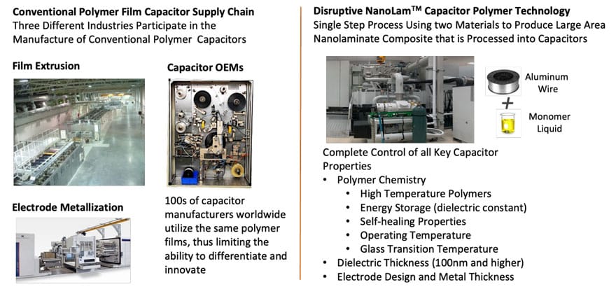
A relatively small number of OEMs produce the polymer films for capacitor applications mainly by an extrusion process that involves elaborate and costly machinery. Film rolls are metallized with different electrode patterns and slit into bobbins that are used to form metallized capacitor rolls, or bobbins of unmetallized films are wound with foil electrodes into polymer film capacitors. In the one-step NanolamTM process, a liquid monomer and aluminum wire are injected into a machine that produces bulk nanolaminate capacitor material. This replaces the film producer, the metallizing OEM and the winding machines used by a capacitor OEM to produce metallized film capacitors.
More importantly all OEMs of conventional metallized film capacitors utilize the same polymer films, which limits innovation and the ability to produce custom dielectrics to suit specific applications. PolyCharge controls all aspects of the capacitor materials and process, including the polymer chemistry, the mechanical and thermal properties of the dielectric, the dielectric constant, the polymer dielectric thickness and the electrode metallization.
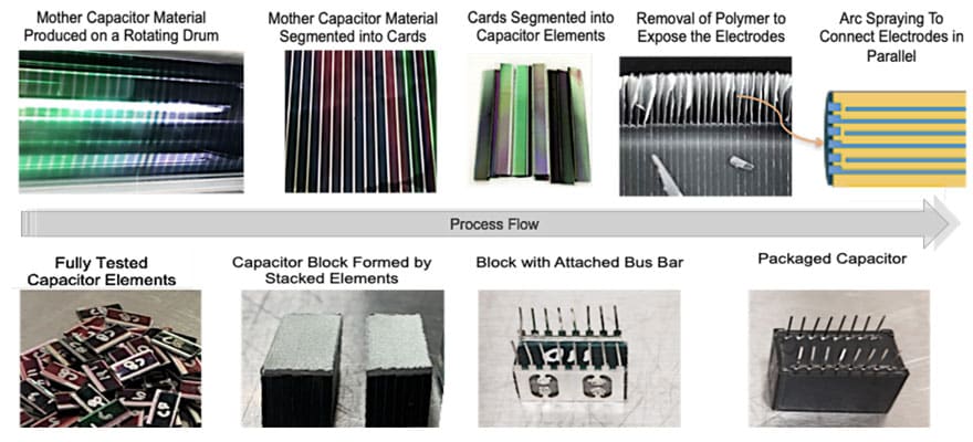
The process steps used to convert the large area nanolaminate material to NanoLamTM capacitors is shown in Figure 2. The nanolaminate “mother” capacitor material with 1000s of capacitor layers is produced on a large process drum that is rotating at 100s ft/min. The process starts by depositing onto the drum a formulated monomer material, that is flash evaporated outside the vacuum chamber. The monomer vapor enters the chamber via a monomer nozzle that is positioned near the drum. The vapor is deposited onto the drum forming a thin liquid layer and it is converted into a cross linked
polymer as it passes in front of an electron beam curtain. Oil microjets are used to deposit very thin strips of oil onto the polymer dielectric, which demetallize the aluminum layer, to form the capacitor electrodes, as well as internal series sections for higher voltage capacitors. An electrode masking system is used to forms areas of thick aluminum (heavy edge) outside the active capacitor area, where electrical contact is made.
4.0 THE POLYMER DIELECTRIC
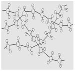
The materials used to formulate the polymer dielectric are polyfunctional acrylate monomers, comprising mono, di and trifunctional components, designed to optimize the dielectric constant, dissipation factor, glass transition and self-healing properties of the capacitor. Major considerations which led to selecting the acrylate monomer chemistry to form high quality capacitor dielectrics include:
- Rapid cure response ensures economical production speeds.
- A wide selection of polymer chemistries with broad range of chemical and physical properties.
- They form amorphous pinhole free films that have excellent breakdown strength and high temperature properties.
- Commercial availability from a number of vendors ensures sufficient supply and low material cost
The Polymer Dielectric is Formed Using Electron Beam Crosslinked Acrylate Monomers (Beta Radiation)
H2C=CHC(O)O R(X) OC(O)CH=CH2
- R = aliphatic, aromatic, cycloaliphatic, etc
- Dielectric Constants: 2.7 < k < 9
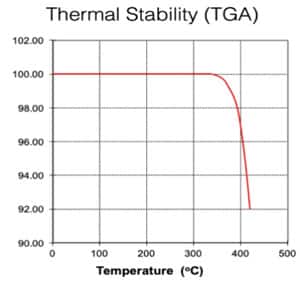
4.1 Thermal Stability
NanoLamTM capacitors are designed to operate in the temperature range of -60oC to 140oC. The maximum operating temperature is limited more by the capacitor package than the multilayer capacitor elements. Figure 3 shows a typical Thermogravimetric Analysis (TGA) scan of a NanoLamTM polymer dielectric. During processing NanoLamTM capacitor material is exposed to temperatures as high as 250oC. The polymer is designed with a glass transition temperature (Tg) greater than 200oC.
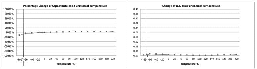
The Tg determines the stability of the dissipation factor as a function of temperature. Polar dielectric materials in general should not be operated above the Tg to avoid an increase in DF and in the case of metallized polymer dielectrics, to avoid an increase in moisture absorption, which results from the mechanical relaxation that takes place above the Tg. An increase in moisture absorption will accelerate in capacitance loss as well as an increase in ESR due to electrode corrosion. Figure 4 shows an excellent stability of dielectric properties in the temperature range of -200oC to 200oC.
4.2 Breakdown Strength
The intrinsic breakdown strength of the NanoLam dielectrics is greater than 1000V/µm, which is significantly higher than polymer film dielectrics. The high breakdown strength is a result of mainly two factors: a) the dielectric thickness and b) optimization of self-healing properties.
4.2.1 Dielectric Thickness
We have found that as the thickness of the polymer dielectrics decreases the breakdown strength of the capacitors increases. Theoretically it can be shown that the breakdown field, Eb is proportional to the dielectric thickness as expressed by the relationship: Eb ∝ e-kx. Experimental data also shows that NanoLam TM capacitor energy density increases as the dielectric layer thickness decreases below about one micrometer. This behavior is independent of the
dielectric constant of the polymer material [7,8].
4.2.2 Self-healing Properties
As in conventional metallized film capacitors, the self-healing property is a function of the electrode thickness/resistivity, and the chemical structure and physical properties of the polymer dielectric. In NanolamTM capacitors, the high temperature polymer dielectric allows for a relatively thick heavy edge to be deposited, which facilitates high rms and di/dt currents, as well as a higher ohm/sq in the active electrode area, which enhances the self-healing properties.
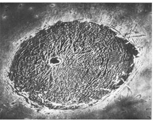
The self-healing process is a surface phenomenon (Figure 5), that is not different than tracking properties of dielectric materials used in high voltage insulators. During a breakdown event the arc temperature causes the surface of the polymer to pyrolyze, which de-hydrogenates the polymer, leaving carbon behind which prolongs the life and travel of the arc. This increases the probability of a thermal runaway condition that can lead to a catastrophic failure. A dielectric with good self-healing properties will facilitate carbon removal by the formation of CO, CO2, CH3, CH4, and other hydrocarbon gases.
The NanoLamTM dielectric is produced with a monomer that is formulated to maximize the O:C and H:C ratios in the molecular structure of the cross-linked polymer, which maximizes the effectiveness of the self-healing process. The presence of oxygen also serves to convert the Al electrode to Al2O3. It should be noted that polymer films such as polypropylene that do not have oxygen in their chemical structure, rely on the micro-air gap for the supply of oxygen. The lack of an air gap due to a capacitor roll wound too tight or excessively pressed into an oval, can compromise the self-healing properties. High temperature conventional capacitor film dielectrics such as polyphenylene sulfide (PPS) and polyimide (PI) have poor self-healing properties due to the low O:C and H:C ratios in their molecular structure.
5.0 EXAMPLES OF NANOLAMTM CAPACITORS FOR SPACE APPLICATIONS
5.1 NanoLamTM Capacitors for a NASA DPCS system
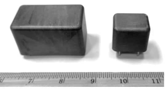
Figure 6, shows Energy Buffer and DC-link capacitors for an NASA Advance Controller Unit used in a Dynamic Power Conversion System (DPCS) for a Lunar application. The capacitors are de-designed to operate over a wide range of temperatures in the presence of radiation generated by the DPCS. The capacitors are packaged in high temperature Liquid Crystal Polymer (LCP) boxes.
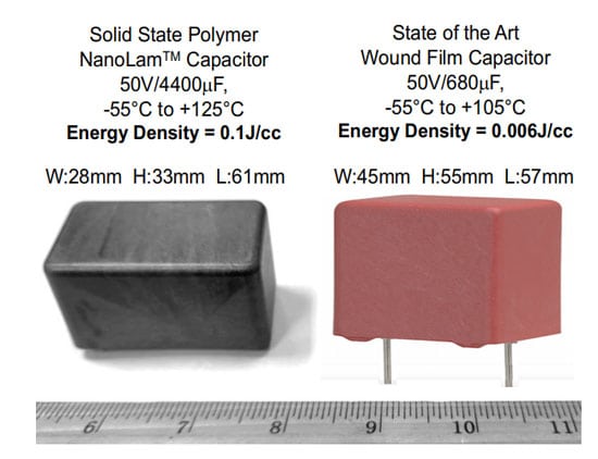
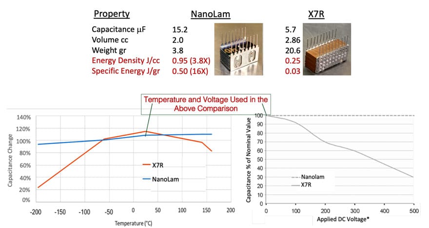
The combination of high and low temperatures with the presence of radiation and the requirement for stable dielectric properties (with temperature and bias) imposes a severe limitation on the type of capacitors that can be used for this application. A conventional polymer film capacitor will provide the stability of capacitance with temperature and bias, but it will require certain level of mechanical protection from exposure to radiation. A comparison of a state-of-the-art metallized polymer film capacitor and the energy Buffer NanoLamTM capacitor is shown in Figure 7.
Conventional low voltage high microfarad metallized film capacitors for DC applications, are produced using an ultrathin polyester film that has the same dielectric constant as the NanoLamTM polymer dielectric used in this application (k=3.2). The polyester film at a thickness of 1.2µm is limited to a temperature of 105o C and has an intrinsic breakdown strength <500V/µm. In contrast The NanoLamTM in Figure 7 has a dielectric thickness of 300nm and an intrinsic breakdown strength of the order of 1000V/µm. As a result, the NanoLamTM capacitor has 16X higher energy density, not including the weight and volume of a protective shield that will be necessary for the metallized film capacitor.
5.2 NanoLamTM Capacitors for a Hall Thruster PPU
Hall thruster Power Processing Units (PPUs) have an input voltage requirement typically in the range of 80V to 160V although systems are developed with bus voltages as low as 28V and as high as 300V. A NASA 120V PPU that utilized high frequency MOSFETS in the inverter circuit was tested using an 5mF/500V MLCC DC-link capacitor. Benchtop testing revealed that the MLCC parts experienced microcracking failures, that were attributed to the piezoelectric vibration caused by the switching frequency or secondary harmonics. A NanoLamTM capacitor shown in Figure 8, was developed to replace the MLCC. Energy Density and Specific Energy comparison between the two technologies is shown in Figure 8. When considering long term reliability, the NanoLamTM capacitor do not fail short. Instead, they will experience some capacitance loss if operated at high temperature and humidity over 1000s of hrs. In the absence of humidity the capacitance will remain within the initial +/- 5% specification for over 100,000 hrs
* Loss of capacitance with volage can vary in X7R products from one capacitor OEM to another. The X7R capacitance variation with voltage is published by Johansen Ceramics.
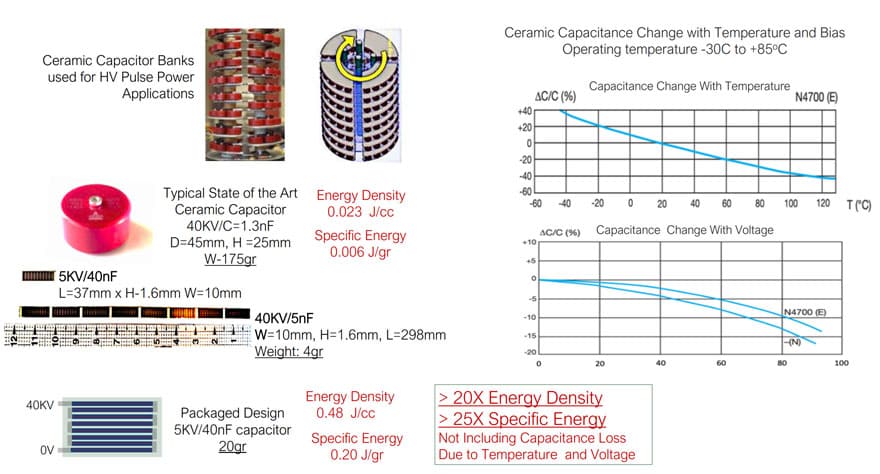
5.3 Pulse Power Applications
Potential pulse power applications for space platforms include systems for High Energy Lasers and High-Power Microwaves. High voltage pulse capacitors are a key and often a critical component of different pulse power systems. Figure 9 shows a comparison of ceramic capacitors currently used to generate high energy microwave pulses and recently developed HV NanoLamTM capacitors with high dV/dt performance, capable of replacing film/foil capacitors designed to discharge high peak currents.
6.0 CONCLUSIONS
NanoLamTM capacitors, designed for use in power supply units of spacecraft, probes, rovers and satellites exposed to extreme conditions of temperature and radiation, have several differentiating features when compared to polymer film and Ceramic capacitors, that lead to superior energy density and specific energy. These include:
- High temperature thermoset polymer dielectrics
- High Breakdown strength nanothick dielectric layers
- Optimized O:C and H:C chemistry to maximize self-healing performance
- High thermal conductivity
- High RMS ripple current capacity and excellent dV/dt performance
- Prismatic shape with low ESR and ESL
- Manufactured using a single step process allowing a capacitor OEM to control most key capacitor parameters including:
- Dielectric thickness
- Dielectric constant
- Glass transition temperature
- Self-healing properties
- Electrode metallization
- The solid-state nature of the NanoLamTM capacitors eliminates air gaps between capacitor layers which virtually eliminates the presence of corona
7.0 Bibliography
- F. Teyssandier and D. Prele, “Commercially Available Capacitors at Cryogenic Temperatures”, Ninth International Workshop on Low Temperature Electronics – WOLTE9, Jun 2010, Guaruja, Brazil.
- A. Teverovsky, “Reliability of Electronics at Cryogenic Temperatures An Approach to Reliability Testing of High-Voltage Drivers at Cryogenic Temperatures”, NASA Electronic Parts and Packaging Program (NEPP), QSS Group, Inc. Code 562, 2005, NASA GSFC,
- Ming-Jen Pan, “Performance of Capacitors Under DC Bias at Liquid nitrogen Temperature” US Naval Research Laboratory, Multifunctional Materials Branch, Code 6350, published by Elsevier, Cryogenics, 03, 2005
- Private communication by Louis Pinero of NASA GRC, based on failure analysis of MLCCs used in High Power Hall Thruster PPUs
- A. Yializis, A Disruptive DC-Link Capacitor Technology for Use in Electric Drive Inverters, European Passive Components Institute 10-13th September 2019, Bucharest, Romania
- A. Yializis and Yuji Ozaki, “Solid State Polymer Multilayer (PML) Capacitors” Electronic Components Industry Association, Huston TX, March 2013 – Best Conference Paper Award
- A. Yializis, G. Goodyear, “Advance High Energy Density Capacitors”, Advance Capacitors World Summit, March 31, 2009, Lajolla, Ca.
- A. Yializis and T.A. Miller, “Electrostatic Supercapacitors”, Fifth International Seminar on Double Layer Capacitors and Similar Energy Storage Devices, Dec. 4-6, Boca Raton, FL.,(1995).


