Passive Components Blog
No Result
View All Result
  • Home
  • NewsFilter
    • All
    • Aerospace & Defence
    • Antenna
    • Applications
    • Automotive
    • Capacitors
    • Circuit Protection Devices
    • electro-mechanical news
    • Filters
    • Fuses
    • Inductors
    • Industrial
    • Integrated Passives
    • inter-connect news
    • Market & Supply Chain
    • Market Insights
    • Medical
    • Modelling and Simulation
    • New Materials & Supply
    • New Technologies
    • Non-linear Passives
    • Oscillators
    • Passive Sensors News
    • Resistors
    • RF & Microwave
    • Telecommunication
    • Weekly Digest

    Modelithics Releases COMPLETE v26.1 for Keysight ADS

    April 2026 Interconnect, Passives and Electromechanical Components Market Insights

    SPICE Simulation of Non-Linear Resistors: Vishay’s Thermistor and PPTC Modelling Ecosystem

    KYOCERA AVX Introduces Traction‑Grade DC Link Film Capacitors

    When More Capacitance Hurts Reliability: The Role of the Metallic Skeleton in Tantalum Anodes

    Why Power Inductors Use a Ferrite Core With an Air Gap

    Wk 16 Electronics Supply Chain Digest

    YAGEO Introduces High‑Current Y2/X1 Film Capacitors for Wide-bandgap Power Systems

    Amphenol Explanded Liquid Cooling Connectors for AI, ESS and EV Systems

    Trending Tags

    • Ripple Current
    • RF
    • Leakage Current
    • Tantalum vs Ceramic
    • Snubber
    • Low ESR
    • Feedthrough
    • Derating
    • Dielectric Constant
    • New Products
    • Market Reports
  • VideoFilter
    • All
    • Antenna videos
    • Capacitor videos
    • Circuit Protection Video
    • Filter videos
    • Fuse videos
    • Inductor videos
    • Inter-Connect Video
    • Non-linear passives videos
    • Oscillator videos
    • Passive sensors videos
    • Resistor videos

    Why Power Inductors Use a Ferrite Core With an Air Gap

    Transformer-Based Power-Line Harvester Magnetic Design

    Thermal Modeling of Magnetics

    Standard vs Planar LLC transformers Comparison for Battery Chargers

    How Modern Tools Model Magnetic Components for Power Electronics

    Advanced Loss Modeling for Planar Magnetics in the Frenetic Planar Tool

    2026 Power Magnetics Design Trends: Flyback, DAB and Planar

    Enabling Software‑Defined Vehicle Architectures: Automotive Ethernet and Zonal Smart Power

    Calculating Resistance Value of a Flyback RC Snubber 

    Trending Tags

    • Capacitors explained
    • Inductors explained
    • Resistors explained
    • Filters explained
    • Application Video Guidelines
    • EMC
    • New Products
    • Ripple Current
    • Simulation
    • Tantalum vs Ceramic
  • Knowledge Blog
  • DossiersNew
  • Suppliers
    • Who is Who
  • PCNS
    • PCNS 2025
    • PCNS 2023
    • PCNS 2021
    • PCNS 2019
    • PCNS 2017
  • Events
No Result
View All Result
Passive Components Blog
No Result
View All Result

How to Optimize a Magnetic Design by Adjusting Core and Windings Parameters

10.10.2023
Reading Time: 6 mins read
A A

Pablo Blázquez, Power Εlectronics Εngineer of Frenetic in this blog discuss how to balance a Magnetic design by adjusting certain parameters in the core and windings.

One of the key challenges in Magnetic design is to achieve a balance between different performance parameters such as power efficiency, magnetic flux density, and operating frequency. This is particularly important in those applications where the device is expected to operate under different load conditions or in a range of environments.

RelatedPosts

Modeling Planar Magnetics Temperature: Practical Guidelines for Power Electronics Engineers

LLC Transformer: Designing a 2 kW LLC Transformer with Integrated Resonant Inductor

Thermal Modeling of Magnetics

In this edition, we will explore some of the techniques and principles involved in the balancing of a Magnetic design. We will focus on the role of both the core and the windings in achieving optimal performance, and we will discuss how modifications to these parameters can affect the overall magnetic properties of the device.

Whether you are an engineer, a researcher, or someone with an interest in Electronics, I hope that this post will provide you with valuable insights and ideas for improving the performance of your Magnetic designs.

Balance, Why?

Let’s start with a simple question: why do we want the losses to be perfectly distributed between core and windings in our Magnetic? In a magnetic component, such as a Transformer or an Inductor, energy losses can occur in both the core and the windings. The losses in the core are primarily due to hysteresis and eddy currents, while those in the windings are due to the resistance of the wire.

Ideally, we want the losses to be evenly distributed between the core and the windings, because this can improve the overall efficiency and reliability of the magnetic itself. If the losses are concentrated primarily in one area, for example in the core, it can lead to increased heating and temperature rise, which can therefore degrade the performance of the component and reduce its lifespan.

By distributing the losses evenly between the core and the windings, we can ensure that the heat generated is dissipated in a more uniform way, reducing the risk of hot spots and thermal stress. Additionally, a more balanced distribution of losses can also help to reduce the overall size and weight of the component, making it more cost-effective and easier to integrate into a wide range of applications.

In summary, distributing the losses evenly between the core and the windings is key to the optimization of the efficiency, reliability, and performance of our magnetic components.

How you can do that?

There are several ways to balance losses between the core and the windings in our Magnetic. Let’s analyze them starting from a design that you can access here:

1. Choose the right core material

The choice of core material can have a significant impact on the distribution of losses. For example, using a core material with lower hysteresis losses can help you to reduce losses in the core. In Figure 1 you can see a comparison between the original design and two slightly different versions:

Figure 1. 3C97 VS 3C90 VS KoolMu 60 magnetic core material comparison

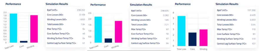
The first on the left is the original design. In the second version we have changed the original core material (Ferrite 3C97) to 3C90, while in the third one we have switched to powder material KoolMu 60. It is clearly visible that the core losses increase in both cases and, although the powder material provides more balance, it results in considerably higher losses.

2. Adjust the core size

The size of the core can also affect the distribution of losses: by Increasing the core size, you can reduce the magnetic flux density and decrease core losses. Figure 2 shows the result of increasing the core size compared to the original design.

Figure 2. PQ35 VS PQ40 VS E41 magnetic core material comparison

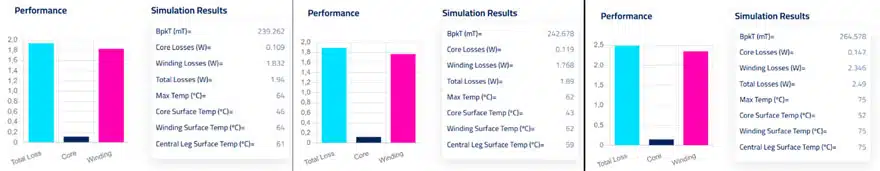
You can see how, in both examples, we have slightly increased the core losses. However, reducing the core temperature in the PQ 40 seems to have affected the overall temperature and this can be one of the reasons why the overall losses have decreased.

In the second example, the E41, we get the opposite result. The less efficient E core has raised the core losses and temperature, causing an increase in the winding losses and therefore a growth in the overall losses.

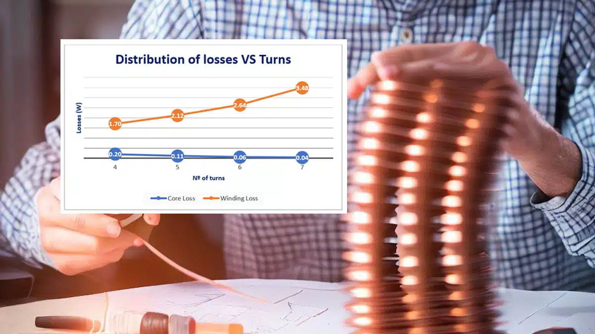
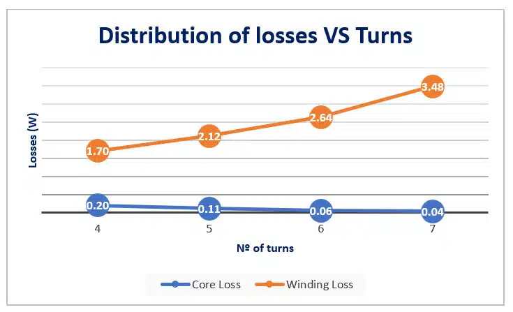
3. Change the number of turns

The number of turns in a magnetic component also affects the distribution of losses. Decreasing the number of turns can help you shift the winding losses to the core. In Figure 3 you can see the effect of changing the number of turns in the overall design: 

Table 1. Nº of turns effect to magnetic design
Figure 3. Losses Evolution with Nº of turns in magnetic design

4. Optimize the wire size

Using the right wire size can reduce the overall losses in the windings.

Figure 4. Different Wires impact comparison

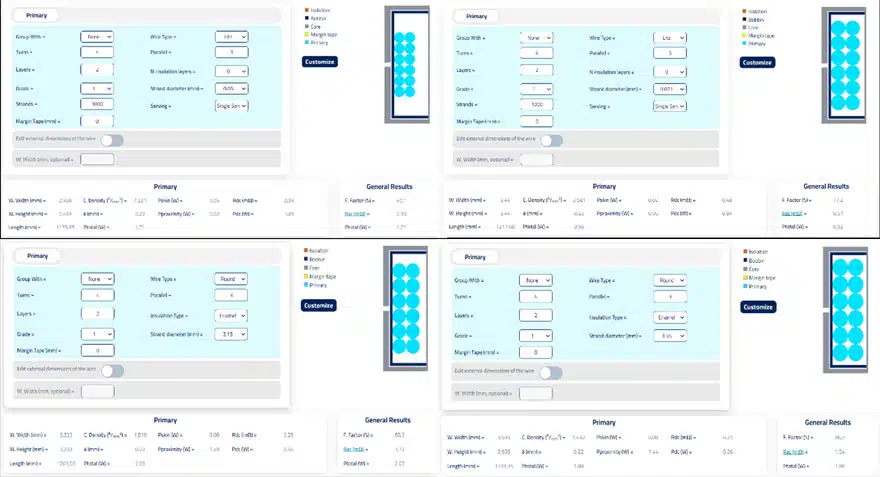
In Figure 4 you can see a comparison between several wires with different sizes and types. We have the litz wires on the top, and the round wires in the bottom. In terms of losses, you can clearly see that litz wire has much lower losses than the round ones. Moreover, in both examples the size incrementation of the wire reduces the overall losses.

5. Adjust the operating frequency

The operating frequency of a magnetic component can also impact the losses distribution. Operating at a lower frequency can help you reduce core losses, while operating at a higher frequency can help you reduce winding losses. You can read more on this topic in post here: Optimal Frequency for a PSFB.

Conclusions

In practice, achieving a perfectly balanced distribution of losses may not always be possible. However, by using a combination of the techniques explained today, it is possible to optimize the design of a magnetic component for a given application and therefore achieve a more balanced losses distribution.

It is completely up to you which options to choose, if not all of them work for you. Just bear in mind that you’re not always going to be able to have a balanced design that meets your requirements, and you might have to make the decision whether to have fewer losses or a balanced design

Related

Source: Frenetic

Recent Posts

Modelithics Releases COMPLETE v26.1 for Keysight ADS

23.4.2026
11

April 2026 Interconnect, Passives and Electromechanical Components Market Insights

22.4.2026
42

Why Power Inductors Use a Ferrite Core With an Air Gap

20.4.2026
41

TDK Introduces High‑Voltage Common‑Mode Chokes for Compact 1250 V DC Converters

16.4.2026
30

Vishay Extends Power Inductors for DC/DC with 1212 Compact Case

16.4.2026
21

Modeling Planar Magnetics Temperature: Practical Guidelines for Power Electronics Engineers

15.4.2026
23

YAGEO Releases Ferrite Shielded Power Inductors for High‑Density Designs

15.4.2026
29

YAGEO Introduces EMI Suppression High‑Current 3‑phase Common Mode Chokes

14.4.2026
35

ECIA March 2026 Industry Pulse Points to Best Sales Climate in Five Years

13.4.2026
54

Upcoming Events

Apr 27
15:00 - 16:00 CEST

Commercial Space Screening Approach for Agile, High-Reliability Payloads

Apr 29
10:00 - 11:00 CDT

SEPIC Design Done Right

Apr 30
10:00 - 11:00 CDT

Programming Embedded Systems

View Calendar

Popular Posts

  • Buck Converter Design and Calculation

    0 shares
    Share 0 Tweet 0
  • Boost Converter Design and Calculation

    0 shares
    Share 0 Tweet 0
  • Flyback Converter Design and Calculation

    0 shares
    Share 0 Tweet 0
  • LLC Resonant Converter Design and Calculation

    0 shares
    Share 0 Tweet 0
  • MLCC and Ceramic Capacitors

    0 shares
    Share 0 Tweet 0
  • Dual Active Bridge (DAB) Topology

    0 shares
    Share 0 Tweet 0
  • Capacitor Charging and Discharging

    0 shares
    Share 0 Tweet 0
  • What Electronics Engineer Needs to Know About Passive Low Pass Filters

    0 shares
    Share 0 Tweet 0
  • Ripple Current and its Effects on the Performance of Capacitors

    3 shares
    Share 3 Tweet 0
  • MLCC Case Sizes Standards Explained

    0 shares
    Share 0 Tweet 0

Newsletter Subscription


Passive Components Blog

© EPCI - Leading Passive Components Educational and Information Site

  • Home
  • Privacy Policy
  • EPCI Membership & Advertisement
  • About

No Result
View All Result
  • Home
  • Knowledge Blog
  • PCNS

© EPCI - Leading Passive Components Educational and Information Site

This website uses cookies. By continuing to use this website you are giving consent to cookies being used. Visit our Privacy and Cookie Policy.
Go to mobile version