Passive Components Blog
No Result
View All Result
  • Home
  • NewsFilter
    • All
    • Aerospace & Defence
    • Antenna
    • Applications
    • Automotive
    • Capacitors
    • Circuit Protection Devices
    • electro-mechanical news
    • Filters
    • Fuses
    • Inductors
    • Industrial
    • Integrated Passives
    • inter-connect news
    • Market & Supply Chain
    • Market Insights
    • Medical
    • Modelling and Simulation
    • New Materials & Supply
    • New Technologies
    • Non-linear Passives
    • Oscillators
    • Passive Sensors News
    • Resistors
    • RF & Microwave
    • Telecommunication
    • Weekly Digest

    Common Mistakes in Flyback Transformer Specs

    Vishay Releases Miniature SMD Trimmers for Harsh Environments

    Würth Elektronik Releases Push-Button and Main Switches

    Littelfuse Unveils High-Precision TMR Angle Magnetic Sensors

    Stackpole Extends Voltage of High Temp Chip Resistors

    High Voltage MLCCs Meeting the Growing Demand for Efficiency in Power Conversion

    Bourns Releases High Power High Ripple Chokes

    KYOCERA AVX Releases Hermaphroditic WTW and WTB Connectors

    Radiation Tolerance of Tantalum and Ceramic Capacitors

    Trending Tags

    • Ripple Current
    • RF
    • Leakage Current
    • Tantalum vs Ceramic
    • Snubber
    • Low ESR
    • Feedthrough
    • Derating
    • Dielectric Constant
    • New Products
    • Market Reports
  • VideoFilter
    • All
    • Antenna videos
    • Capacitor videos
    • Circuit Protection Video
    • Filter videos
    • Fuse videos
    • Inductor videos
    • Inter-Connect Video
    • Non-linear passives videos
    • Oscillator videos
    • Passive sensors videos
    • Resistor videos

    Percolation Phenomenon and Reliability of Molded Power Inductors in DC/DC converters

    Root Causes and Effects of DC Bias and AC in Ceramic Capacitors

    How to Calculate the Output Capacitor for a Switching Power Supply

    Switched Capacitor Converter Explained

    Understanding Inductor Dot Markings and Their Application in LTspice

    Accelerating Full Bridge LLC Resonant Converter Design with Frenetic AI

    Understanding Switched Capacitor Converters

    Coupled Inductors Circuit Model and Examples of its Applications

    Inductor Resonances and its Impact to EMI

    Trending Tags

    • Capacitors explained
    • Inductors explained
    • Resistors explained
    • Filters explained
    • Application Video Guidelines
    • EMC
    • New Products
    • Ripple Current
    • Simulation
    • Tantalum vs Ceramic
  • Knowledge Blog
  • Suppliers
    • Who is Who
  • Events
No Result
View All Result
Passive Components Blog
No Result
View All Result

EMI Filtering: How to Suppress Triacs EMI and RFI Noise

8.8.2022
Reading Time: 2 mins read
A A

Triacs and thyristors (silicon-controlled rectifiers, or SCRs) are used in power-switching applications because these can handle high voltages and currents. Triac switching circuits are more prone to noise creating a burst of electric pulses that cause electromagnetic interference (EMI) and radio frequency interference (RFI) in the circuit. Read how to design EMI filtering and suppress this impact.

Noise is generated in all semiconductor devices including triacs. Triacs are used in such power-switching applications as inverter- or motor-control circuits. Triacs and thyristors (silicon-controlled rectifiers, or SCRs) are used in power-switching applications because these can handle high voltages and currents.

RelatedPosts

Common Mistakes in Flyback Transformer Specs

Vishay Releases Miniature SMD Trimmers for Harsh Environments

Würth Elektronik Releases Push-Button and Main Switches

A typical triac application circuit is shown in Fig. 1. Basically, a triac has two thyristors—one conducts during positive half cycle of input voltage and the other during negative half cycle. When the gate terminal is triggered, current can flow either from MT1 to MT2, or from MT2 to MT1.

Typical triac switching application circuit
Figure 1: Typical triac switching application circuit

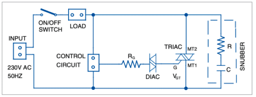
Trigger voltage (VGT) applied to the gate terminal can either be positive or negative with respect to MT2. But these do not trigger symmetrically, causing differences in positive and negative half cycles of the output. This leads to high level harmonics inducing noise and causes electromagnetic interference (EMI) in the circuit.

Triac switching circuits are more prone to noise because when load is turned on, current rises from zero to maximum value suddenly, creating a burst of electric pulses that cause radio frequency interference (RFI). The larger the load current, the worse will be the interference.

In electrically-noisy environments, spurious gate triggering can occur if noise voltage on the gate exceeds VGT and enough gate current flows to initiate regenerative action within the triac.

Harmonics are strong enough to create malfunctions and errors in sensitive electronic devices like computers. The little noise induced in power lines of the PCs may create problems in the most unpredictable ways.

Some ways to minimise noise in a triac circuit are:

  1. Keep gate connections as short as possible. If these are hard-wired, you can use twisted pair wires or even shielded cables to minimise noise pickup.
  2. Add a suitable resistor between the gate and MT1 to reduce gate sensitivity.
  3. Mount the triac leaded package down flat on the PCB or cabinet to stop any vibration-causing noise.
  4. Place a diac at the gate of triac for cleaner switching.
  5. Use an RC snubber circuit between MT1 and MT2 to prevent premature triggering caused by voltage spikes in the AC supply or inductive loads such as motors.
  6. Use a gate filter to reduce noise coming from AC mains.

Related

Source: ElectronicsForu

Recent Posts

Common Mistakes in Flyback Transformer Specs

15.8.2025
3

High Voltage MLCCs Meeting the Growing Demand for Efficiency in Power Conversion

12.8.2025
48

Radiation Tolerance of Tantalum and Ceramic Capacitors

8.8.2025
60

Percolation Phenomenon and Reliability of Molded Power Inductors in DC/DC converters

6.8.2025
34

Root Causes and Effects of DC Bias and AC in Ceramic Capacitors

6.8.2025
47

How to Calculate the Output Capacitor for a Switching Power Supply

6.8.2025
42

Additive Manufacturing of Mn-Zn Ferrite Planar Inductors

4.8.2025
22

Evaluation and Modeling of Supercapacitors for Reliability of Lifetime Predictions

4.8.2025
32

Würth Elektronik Expands MagI³C with Variable Step-Down Modules

30.7.2025
25

Switched Capacitor Converter Explained

28.7.2025
47

Upcoming Events

Aug 27
17:00 - 18:00 CEST

Capacitor Assemblies for High-Power Circuit Designs

Sep 3
15:30 - 17:30 CEST

How to Choose Your Magnetic Supplier

Sep 22
September 22 @ 13:00 - September 25 @ 15:15 EDT

Pre Cap Visual Inspection per Mil-Std-883 (TM 2017)

Sep 30
September 30 @ 12:00 - October 2 @ 14:00 EDT

MIL-Std-883 TM 2010

Oct 17
12:00 - 14:00 EDT

External Visual Inspection per MIL-STD-883 TM 2009

View Calendar

Popular Posts

  • Buck Converter Design and Calculation

    0 shares
    Share 0 Tweet 0
  • Boost Converter Design and Calculation

    0 shares
    Share 0 Tweet 0
  • Flyback Converter Design and Calculation

    0 shares
    Share 0 Tweet 0
  • LLC Resonant Converter Design and Calculation

    0 shares
    Share 0 Tweet 0
  • What is a Dielectric Constant and DF of Plastic Materials?

    4 shares
    Share 4 Tweet 0
  • Ripple Current and its Effects on the Performance of Capacitors

    3 shares
    Share 3 Tweet 0
  • Dual Active Bridge (DAB) Topology Explained

    0 shares
    Share 0 Tweet 0
  • How to Design an Inductor

    0 shares
    Share 0 Tweet 0
  • MLCC Case Sizes Standards Explained

    0 shares
    Share 0 Tweet 0
  • MLCC and Ceramic Capacitors

    0 shares
    Share 0 Tweet 0

Newsletter Subscription


Passive Components Blog

© EPCI - Leading Passive Components Educational and Information Site

  • Home
  • Privacy Policy
  • EPCI Membership & Advertisement
  • About

No Result
View All Result
  • Home
  • Knowledge Blog
  • Premium Suppliers

© EPCI - Leading Passive Components Educational and Information Site

This website uses cookies. By continuing to use this website you are giving consent to cookies being used. Visit our Privacy and Cookie Policy.
Go to mobile version