


Researchers from PennState, USA published scientific paper entitled “Impact of thermal crosstalk on dependent failure rates of multilayer ceramic capacitors undergoing lifetime testing” in Journal of Applied Physics.
The study investigates the impact of thermal crosstalk on the failure rates of multilayer ceramic capacitors (MLCCs) during lifetime testing.
The research focuses on the degradation of BaTiO3-based dielectric capacitor materials and how thermal crosstalk influences dependent and independent failure rates.
Using finite element analysis thermal modeling and infrared thermography, the study examines the effects of circuit layout and component spacing on heat dissipation and thermal crosstalk under various electrical stress conditions.
Key findings include:
- Thermal crosstalk significantly affects the failure rates of MLCCs, with closer spacing between components leading to higher failure rates.
- The β′ factor is used to quantify the impact of common cause failures due to thermal crosstalk.
- Experimental and statistical analyses show that reducing thermal crosstalk can improve the reliability of MLCCs.
- The study highlights the importance of optimizing circuit layout design to mitigate dependent failures and enhance overall reliability.
The research provides valuable insights into the relationship between MLCC failure testing and operational lifetime implications, emphasizing the need for careful consideration of thermal management in high-density electronic circuits.
Abstract
Several studies have examined the degradation of BaTiO3-based dielectric capacitors, focusing on composition, defect chemistry, and microstructural design to limit oxygen vacancy electromigration under electric fields at finite temperatures. Electromigration is a key factor in determining capacitor failure rates in multilayer ceramic capacitors (MLCCs) during highly accelerated lifetime testing (HALT), which assesses the mean time to failure (MTTF) of MLCCs on printed circuit boards (PCBs). Traditionally, these failures are seen as independent, with no component interaction on the PCB.
Introduction
This study uses a Physics of Failure (PoF) approach to analyze transient degradation and its effect on MLCC reliability, particularly thermal crosstalk. Finite element analysis and infrared thermography were employed to evaluate circuit layout and component spacing on heat dissipation and thermal crosstalk under various electrical stresses. The study identifies dependent and independent failures under HALT using a β′ factor, which indicates common cause failures due to thermal crosstalk.
Experimental and statistical analyses evaluated the β′ factor concerning temperature, voltage, and component spacing. These findings underscore the need to understand reliability testing data and optimize high-density circuit layouts to reduce dependent failures, enhancing overall reliability and guiding better design and packaging strategies.
As electronics evolve toward higher density and power, miniaturization in hybrid circuits is achieved by reducing component size and spacing. This trend challenges device reliability and thermal management. The work focuses on base metal electrode (BME) MLCCs, the most common passive components in modern electronics. The number of MLCCs is increasing to meet circuit capacitive demands. Among MLCC failure mechanisms under electrical bias, time-dependent degradation is particularly interesting and requires further understanding to mitigate risks.
MLCCs perform various functions in electronic circuits, such as charge storage, DC blocking, noise and frequency filtering, and circuit tuning. Under DC or AC bias with ripples, MLCCs experience time-dependent degradation due to oxygen vacancy electromigration, reducing insulation resistance. Mitigation strategies include compositional development, grain size reduction, microstructural development like core–shell structures, and electrode roughness reduction in BaTiO3-based MLCCs. These developments tailor dielectric temperature dependence while limiting oxygen vacancy concentrations and mobilities. Materials in MLCCs must be designed to restrict oxygen vacancy electromigration.
Recent reliability analysis advancements emphasize the PoF approach, moving beyond traditional empirical models. PoF explores how external stressors, like heat, affect components and their collective impact on system reliability, providing a comprehensive understanding of component behavior and failure dynamics. When assessing MLCC reliability, HALT is crucial in determining voltage and temperature ratings under long-term conditions. Understanding failure nature and probability under HALT is essential. Reliability data from HALT samples must represent a larger production batch. Under accelerated conditions of higher voltage and temperatures, predictions about MLCC component lifetime under operating conditions are necessary. Typically, data are analyzed from MTTF under specific voltage and temperature conditions. Two approaches are used to extrapolate MTTF under various conditions: the Eyring Equation and Tipping point model. Under HALT conditions, MLCC components must be mounted in fixtures or PCBs to ensure independent failures and help identify a single root cause of failure with well-processed samples. Ideally, independent failure events occur across multiple MLCC components without affecting neighboring ones in the HALT.
Results and Discussion
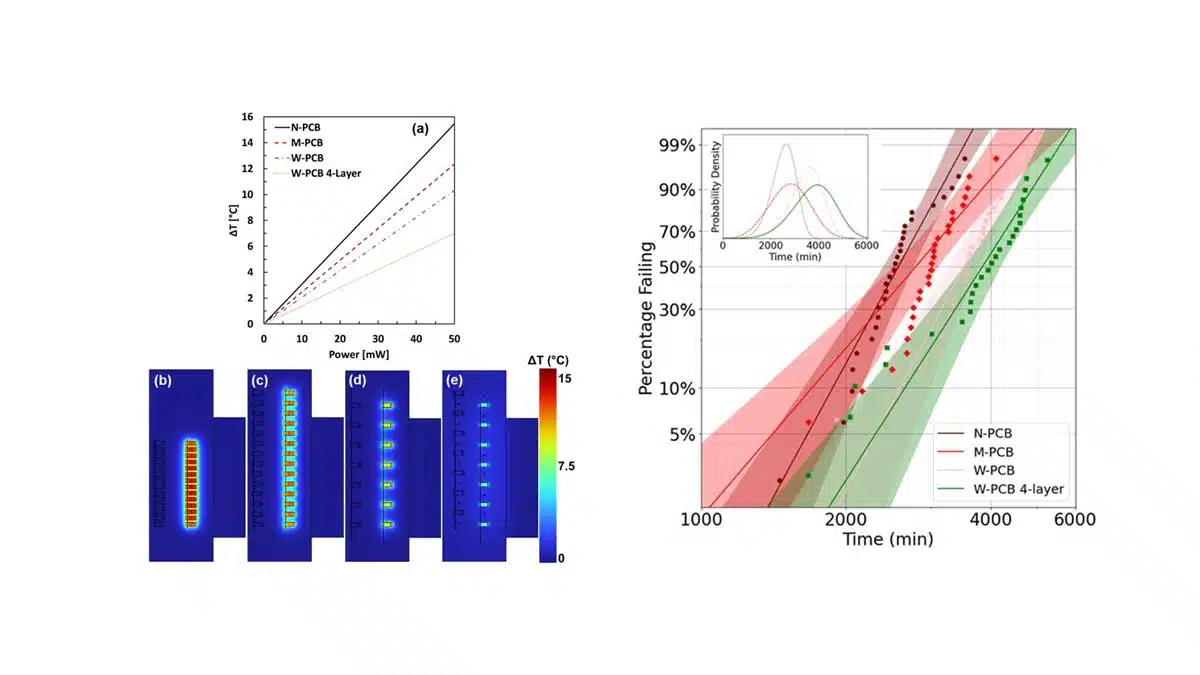
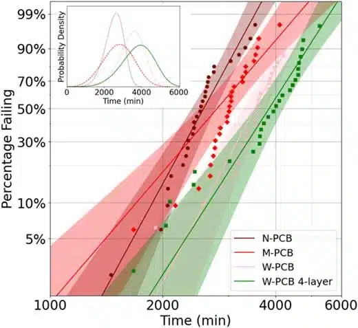
The HALT results highlighted in Fig.1. below demonstrate the impact of different PCB designs on failure distribution. Decreasing the spacing between MLCCs shortens their lifetime. This impact is quantified by analyzing the α and β values of the Weibull distribution for the MLCCs failure time distribution and summarized in Table I. A reduction in the α value, along with an increase in the β value, was observed for MLCCs mounted on the N-PCB compared to those on the M-PCB. These data indicate that the MLCCs mounted closer together tend to have a shorter MTTF. These findings suggest that thermal crosstalk among mounted MLCCs serves as a catalyst for their failures. Thermal analysis was performed to further explain the observed trend.
| PCBs | α (min) | β | 1000λ |
|---|---|---|---|
| Narrow spacing (N) | 2700 ± 100 | 6.0 ± 0.8 | 0.37 ± 0.01 |
| Moderate spacing (M) | 3100 ± 200 | 3.8 ± 0.6 | 0.32 ± 0.02 |
| Wide spacing (W) | 3700 ± 100 | 6.1 ± 0.9 | 0.27 ± 0.01 |
| Wide spacing (four-layer) | 4100 ± 200 | 5.1 ± 0.8 | 0.24 ± 0.01 |
Summary and Conclusions
The critical role of component spacing in managing thermal crosstalk becomes evident as a population of MLCC components undergo degradation. As individual components start to heat through a Joule heating process, they can perturb the degradation rate of neighboring components on the circuit board. Through FEA thermal modeling, IR thermography, HALT, and a statistical analysis of dependent and independent failure rates, these studies evaluate the impact of spacing, voltage, and ambient temperature on different circuit boards.
MLCC component spacing significantly affects thermal interactions, with closer spacings, like those observed on the N-PCB, leading to more pronounced thermal crosstalk. This underscores the need for strategic spatial separation and thermal management in circuit design to ensure component integrity in densely packed circuits and emphasizes the necessity of accounting for both dependent and independent failures in HALT to comprehensively understand MLCC failure dynamics.
The statistical β′ factor analyses conducted in this study revealed correlations between β′, temperature, voltage, and component spacing. The minimal sensitivity of β′ to the ambient temperature in the testing range of 145–155 °C was supported by thermal modeling. However, the linear relationships of β′ with voltage and spacing are found. The weakest components in the first quartile of the lifetime distribution become sources of the thermal crosstalk, driving up the failure rate.
The extent of this effect depends on the operating voltage and the component spacings in each circuit board design. Therefore, understanding and quantifying the failure-dependent factor are crucial for correlating independent failure distributions observed during HALT. The critical findings highlight the importance of strategic circuit design and packaging to more effectively mitigate dependent failures in similar components, such as capacitor arrays. As the electronics industry continues to push toward smaller and more densely packed circuits, the findings from this study highlight the increasing importance of employing standardized methods for failure analysis and advanced physical models for circuit design.
Read the full article here:
Pedram Yousefian, Daniel C. Shoemaker, Javier Mena-Garcia, Michael Norrell, Jeff Long, Sukwon Choi, Clive A. Randall; Impact of thermal crosstalk on dependent failure rates of multilayer ceramic capacitors undergoing lifetime testing. J. Appl. Phys. 21 January 2025; 137 (3): 034104. https://doi.org/10.1063/5.0245201


