Passive Components Blog
No Result
View All Result
  • Home
  • NewsFilter
    • All
    • Aerospace & Defence
    • Antenna
    • Applications
    • Automotive
    • Capacitors
    • Circuit Protection Devices
    • electro-mechanical news
    • Filters
    • Fuses
    • Inductors
    • Industrial
    • Integrated Passives
    • inter-connect news
    • Market & Supply Chain
    • Market Insights
    • Medical
    • Modelling and Simulation
    • New Materials & Supply
    • New Technologies
    • Non-linear Passives
    • Oscillators
    • Passive Sensors News
    • Resistors
    • RF & Microwave
    • Telecommunication
    • Weekly Digest

    3-Phase EMI Filter Design, Simulation, Calculation and Test

    YAGEO Unveils Compact 2.4 GHz SMD Antenna

    KYOCERA AVX Releases Antenna for Iridium Satellite IoT Applications

    Molex Releases Industry-First Quad-Row Board-to-Board Connectors with EMI Shields

    Image credit: Samtec

    How to Match the Right Connector with Protocol Requirements

    Smoltek CNF-MIM Capacitors Pass 1,000h Reliability Test

    Capacitor Lead Times: October 2025

    Paumanok Unveils Aluminum Capacitor Foils World Markets Study 2025-2030

    Coilcraft Introduces Ultra-Low Loss Shielded Power Inductors

    Trending Tags

    • Ripple Current
    • RF
    • Leakage Current
    • Tantalum vs Ceramic
    • Snubber
    • Low ESR
    • Feedthrough
    • Derating
    • Dielectric Constant
    • New Products
    • Market Reports
  • VideoFilter
    • All
    • Antenna videos
    • Capacitor videos
    • Circuit Protection Video
    • Filter videos
    • Fuse videos
    • Inductor videos
    • Inter-Connect Video
    • Non-linear passives videos
    • Oscillator videos
    • Passive sensors videos
    • Resistor videos

    3-Phase EMI Filter Design, Simulation, Calculation and Test

    Transformer Design Optimization for Power Electronics Applications

    Common Mode Chokes Selection for RF Circuits in Next-Generation Communication Systems

    Capacitor Self-balancing in a Flying-Capacitor Buck Converter

    How to Select Ferrite Bead for Filtering in Buck Boost Converter

    Power Inductors Future: Minimal Losses and Compact Designs

    Percolation Phenomenon: Degradation of Molded Power Inductors in DC/DC Converters

    Connector PCB Design Challenges

    Efficient Power Converters: Duty Cycle vs Conduction Losses

    Trending Tags

    • Capacitors explained
    • Inductors explained
    • Resistors explained
    • Filters explained
    • Application Video Guidelines
    • EMC
    • New Products
    • Ripple Current
    • Simulation
    • Tantalum vs Ceramic
  • Knowledge Blog
  • Suppliers
    • Who is Who
  • PCNS
    • PCNS 2025
    • PCNS 2023
    • PCNS 2021
    • PCNS 2019
    • PCNS 2017
  • Events
No Result
View All Result
Passive Components Blog
No Result
View All Result

Inductor Simulation with LTSpice

24.8.2022
Reading Time: 4 mins read
A A

With LTSpice, Linear Technology has developed a high quality freeware SPICE simulator with no limitations on nodes or components and whose command set is largely compatible with other SPICE versions.

Here are a few of the software highlights:

RelatedPosts

3-Phase EMI Filter Design, Simulation, Calculation and Test

YAGEO Unveils Compact 2.4 GHz SMD Antenna

KYOCERA AVX Releases Antenna for Iridium Satellite IoT Applications

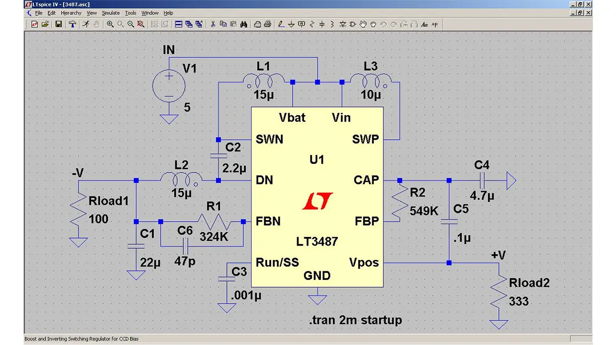
  • Comfortable circuit diagram editor
  • Integrated voltage and current probes
  • Efficiency report for switching controller applications
  • Extensive component library
  • Passive components R,L,C prepared as real components (editable) Library for SMD ferrites Active components Integrated calculation tools for analysis
  • FFT function
  • Extensive help function
  • Automatic update

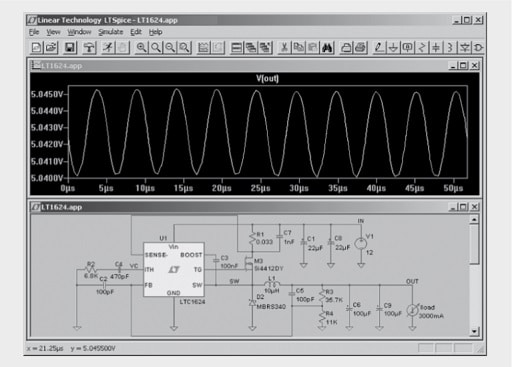
Fig. 1.72: SwitcherCADIII: Screenshot with analyser window and circuit diagram editor

Depending on its position in the circuit diagram editor, the mouse pointer changes between the two probe symbols:

Voltage measurement at the selected node
Current measurement through the selected component

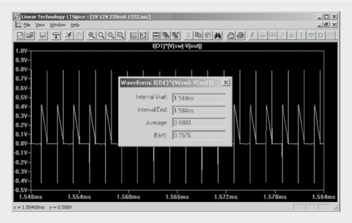
Fig. 1.73: Example of voltage measurement with subsequent curve profile calculation

The component library includes the following Würth Elektronik components as a special feature:

  • SMD ferrite WE-CBF
  • Current-dependent SMD ferrite model (Z[I] for WE-CBF high current SMD ferrite)
  • Current-compensated choke as a broadband model > 1 GHz (subcircuit models)
  • Transformer models (subcircuit models) → in preparation

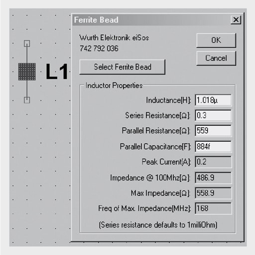
Fig. 1.74: Component library for SMD ferrites

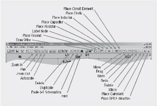
Fig. 1.75: An overview of the most important operating functions

Example of EMC simulation
Simulation of EMC ferrite filters combined with capacitors and resistors represents a typical application example. The simulation achieves the most realistic results the more the RF equivalent circuit diagrams of the components, boards, connectors, leads and sources are taken into account in creating the circuit in the simulation program.

Numerous practical tips for real components and their parasitic component values are to be found in this book; here are some typical values:

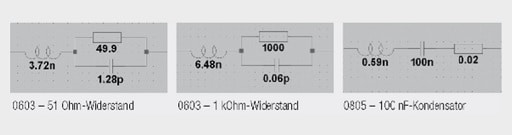
Fig. 1.76: Equivalent circuit diagrams and values for real components

Impedance of the supply voltage connection of an IC
The parasitic elements of an IC are significantly influenced e.g. by the packaging, the internal wire bonds, the number and configuration of the Vcc pins and the die layout. The IC manufacturers increasingly undertake efforts to minimise the parasitic elements and also to specify them. This allows information on the impedance behaviour to be issued.

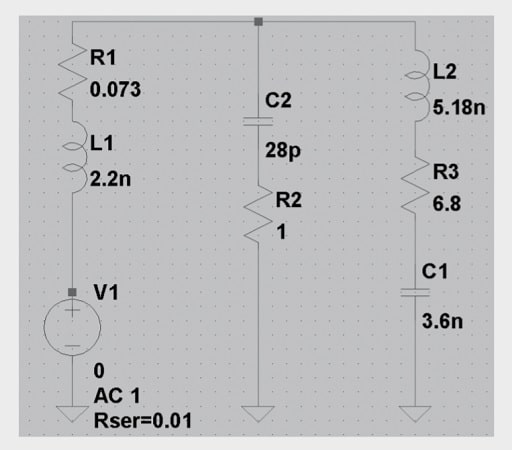
Fig. 1.77: Simulation circuit for the determination of the impedance of an IC

The test circuit shown above represents the IC under investigation with L2/R3/C1, the impedance of the board with C2/R2, and the impedance of the SMA connector used with R1/L1. The simulation now allows the measurement of impedance behaviour at the SMA connector to be shown without complication:

Fig. 1.78: Impedance of an IC → a resonance peak occurs at 500 MHz, the typical impedance is around 10 Ω

Insertion loss of ferrite filters

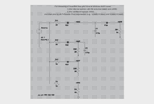
Fig. 1.79: Simulation circuit for the insertion loss of EMC filters

It is important to consider that the unfiltered system (node n004 here) also has to be simulated in the insertion loss simulation to obtain the correct relationship (see → insertion loss).
The special feature of LTspice is that the EMC SMD ferrite is already integrated and can be directly entered in the circuit diagram editor. The filter response can appear as follows and be optimised accordingly:

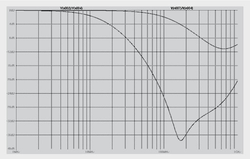
Fig. 1.80: Simulation result for the insertion loss of the EMC filters from Figure 1.79


Related

Recent Posts

3-Phase EMI Filter Design, Simulation, Calculation and Test

6.11.2025
4
Image credit: Samtec

How to Match the Right Connector with Protocol Requirements

6.11.2025
3

Coilcraft Introduces Ultra-Low Loss Shielded Power Inductors

6.11.2025
2

Exxelia Presents Smart Integrated Magnetics Solution at Space Tech Expo 2025 

5.11.2025
13

Murata Expands High Cutoff Frequency Chip Common Mode Chokes

5.11.2025
6

Transformer Design Optimization for Power Electronics Applications

4.11.2025
11

Microhardness — the Hidden Key to Understanding MnOx Cathode Quality in Tantalum Capacitors

3.11.2025
17

Lightweight Model for MLCC Appearance Defect Detection

3.11.2025
20

Bourns Releases High Current Metal Alloy-based, Multilayer Power Chip Inductors

31.10.2025
26

Common Mode Chokes Selection for RF Circuits in Next-Generation Communication Systems

30.10.2025
15

Upcoming Events

Nov 11
17:00 - 18:00 CET

Industrial Applications Demand More from Interconnects in Next-Gen Designs

Nov 12
11:00 - 12:00 CET

PCB Design: Impedance is for everyone!

Nov 12
November 12 @ 12:00 - November 13 @ 14:15 EST

Microelectronic Packaging Failure Modes and Analysis

View Calendar

Popular Posts

  • Buck Converter Design and Calculation

    0 shares
    Share 0 Tweet 0
  • Boost Converter Design and Calculation

    0 shares
    Share 0 Tweet 0
  • LLC Resonant Converter Design and Calculation

    0 shares
    Share 0 Tweet 0
  • Flyback Converter Design and Calculation

    0 shares
    Share 0 Tweet 0
  • Ripple Current and its Effects on the Performance of Capacitors

    3 shares
    Share 3 Tweet 0
  • MLCC and Ceramic Capacitors

    0 shares
    Share 0 Tweet 0
  • Dual Active Bridge (DAB) Topology

    0 shares
    Share 0 Tweet 0
  • What is a Dielectric Constant and DF of Plastic Materials?

    4 shares
    Share 4 Tweet 0
  • SEPIC Converter Design and Calculation

    0 shares
    Share 0 Tweet 0
  • Flying Capacitors

    0 shares
    Share 0 Tweet 0

Newsletter Subscription


Passive Components Blog

© EPCI - Leading Passive Components Educational and Information Site

  • Home
  • Privacy Policy
  • EPCI Membership & Advertisement
  • About

No Result
View All Result
  • Home
  • Knowledge Blog
  • PCNS

© EPCI - Leading Passive Components Educational and Information Site

This website uses cookies. By continuing to use this website you are giving consent to cookies being used. Visit our Privacy and Cookie Policy.
Go to mobile version