Passive Components Blog
No Result
View All Result
  • Home
  • NewsFilter
    • All
    • Aerospace & Defence
    • Antenna
    • Applications
    • Automotive
    • Capacitors
    • Circuit Protection Devices
    • electro-mechanical news
    • Filters
    • Fuses
    • Inductors
    • Industrial
    • Integrated Passives
    • inter-connect news
    • Market & Supply Chain
    • Market Insights
    • Medical
    • Modelling and Simulation
    • New Materials & Supply
    • New Technologies
    • Non-linear Passives
    • Oscillators
    • Passive Sensors News
    • Resistors
    • RF & Microwave
    • Telecommunication
    • Weekly Digest

    Benefits of Tantalum Powder Stress–Strain Curve Evaluation vs Conventional Wet Test

    Electrolyte Selection and Performance in Supercapacitors

    Connector PCB Design Challenges

    Researchers Demonstrated High Energy Ceramic Capacitors Stable in Wide Temperature Range

    Stackpole Offers High Voltage Plate Resistors up to 40KV

    How to Manage Supercapacitors Leakage Current and Self Discharge 

    Qualification of Commercial Supercapacitors for Space Applications

    Experimental Evaluation of Wear Failures in SMD Inductors

    Resonant Capacitors in High-Power Resonant Circuits

    Trending Tags

    • Ripple Current
    • RF
    • Leakage Current
    • Tantalum vs Ceramic
    • Snubber
    • Low ESR
    • Feedthrough
    • Derating
    • Dielectric Constant
    • New Products
    • Market Reports
  • VideoFilter
    • All
    • Antenna videos
    • Capacitor videos
    • Circuit Protection Video
    • Filter videos
    • Fuse videos
    • Inductor videos
    • Inter-Connect Video
    • Non-linear passives videos
    • Oscillator videos
    • Passive sensors videos
    • Resistor videos

    Connector PCB Design Challenges

    Efficient Power Converters: Duty Cycle vs Conduction Losses

    Ripple Steering in Coupled Inductors: SEPIC Case

    SEPIC Converter with Coupled and Uncoupled Inductors

    Coupled Inductors in SEPIC versus Flyback Converters

    Non-Linear MLCC Class II Capacitor Measurements Challenges

    Percolation Phenomenon and Reliability of Molded Power Inductors in DC/DC converters

    Root Causes and Effects of DC Bias and AC in Ceramic Capacitors

    How to Calculate the Output Capacitor for a Switching Power Supply

    Trending Tags

    • Capacitors explained
    • Inductors explained
    • Resistors explained
    • Filters explained
    • Application Video Guidelines
    • EMC
    • New Products
    • Ripple Current
    • Simulation
    • Tantalum vs Ceramic
  • Knowledge Blog
  • Suppliers
    • Who is Who
  • Events
No Result
View All Result
Passive Components Blog
No Result
View All Result

Magnetism, Ampère’s Law and Magnetic Fields Strength

2.5.2025
Reading Time: 7 mins read
A A

The article introduces basic principles of inductive components – Magnetism, Ampère’s Law and Magnetic Fields Strength.

Magnetism

The basis for understanding inductors is provided by magnetism and a few fundamental electromagnetic field laws, revealing clear and fundamental knowledge of inductors and ferrites. The most important phenomena and laws will still perhaps be there from physics lessons:

RelatedPosts

Percolation Phenomenon and Reliability of Molded Power Inductors in DC/DC converters

Inductor Resonances and its Impact to EMI

Rogowski Coil Current Sensor Explained

  • Every magnet has a north and south pole (The earth is an enormous magnet!)
  • If an existing magnet is divided, a new one is created. The magnet so created also has a north and south pole. This division can be performed down to the molecular level without losing the magnetic effect.
  • Every magnet is surrounded by a magnetic field, which is represented by the field line model.
  • Magnetic field lines are closed. They neither beginning nor end. There are magnetizable materials (e.g. iron) and non-magnetizable materials (e.g. aluminum).
  • The following analysis concerns a class of magnetizable materials, the ferromagnetic materials.

Ferromagnetic materials
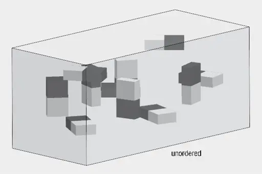
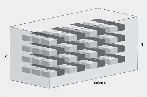
Figure 1. Elementary magnets
Figure 2. magnetic saturation

Every magnetic material is composed of a finite number of the smallest elementary magnets, configured randomly in the unmagnetized state. These orientate themselves under the influence of an external magnetic field.

If all elementary magnets are oriented in the magnetic field, one speaks of saturation of the material.Once the externally applied magnetic field is removed, two effects can occur:

  1. The material becomes nonmagnetic once again: One speaks of a soft magnetic material
  2. The material remains magnetic: One speaks of a hard magnetic material

Ampère’s Law and Magnetic Field Strength
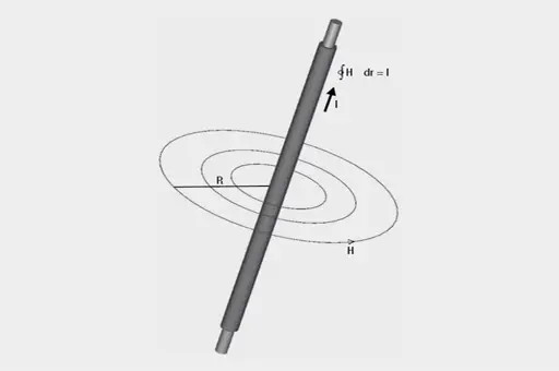
Figure 3. Magnetic field strength H of a long conductor

A magnetic field is created around an electric conductor passing a current. This magnetic force field is a vector quantity perpendicular to the generating current. Field lines represent the magnetic force field. For a current carrying conductor, these form closed concentric circles.

Integrating in a counter clockwise direction along a field line, the H and each distance increment (dr) are always in the same direction. A complete circulation provides the magnetic boundary potential is shown in Figure 3.

If several conductor currents pass through the enclosed area, the sum of the currents must be on the right side of the equation (observing their directional signs):
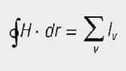
magnetic field equation [1]

The magnetic field is measured by means of the magnetic field strength H and is defined by the currents generated by the field.

Biot-Savart Law

The field strength of any conductor configuration may be determined from the Biot-Savart Law:
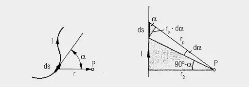
Figure 4. BIOT SAVART’s Law: Describing the field strength outside a straight current conductor

Accordingly, the small section (ds) of the conductor carrying current (I) makes the contribution:

local magnetic field strength equation [2]

(alpha) is the angle between the direction of the line element (ds) and its connection (r) to the point (P) at which the field strength (dH) exists.

Magnetic Field Strength H

The magnetic field strength (H) results from integrating over the entire length of the conductor.

The contour integral of H along a closed line is equal to the total current through the area across this closed path. The magnetic field strength is given by the total current through the surface enclosed by the magnetic field line and the length of this field line.

If it is assumed that the same currents flow in N discrete conductors, as in the case of a coil, the equation simplifies to:
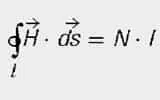
total magnetic field strength equation [3]

N = number of conductors within the closed path l
I = current per conductor

The unit of magnetic field strength (H) is A/m.

Examples:

Straight current conductor
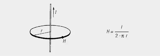
Figure 5. Magnetic field strength (H) of a straight conductor

Long solenoid

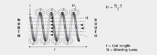
Figure 6. Magnetic field strength H in a solenoid

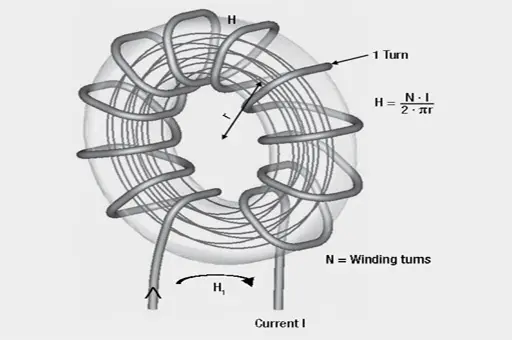
Toroidal coil

Figure 7. Magnetic field strength H of a toroidal coil

The Figure 6. illustration shows the size of the magnetic field strength (H) inside a long solenoid to be dependent on the current I, the coil length l and the winding turns N.
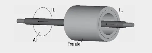
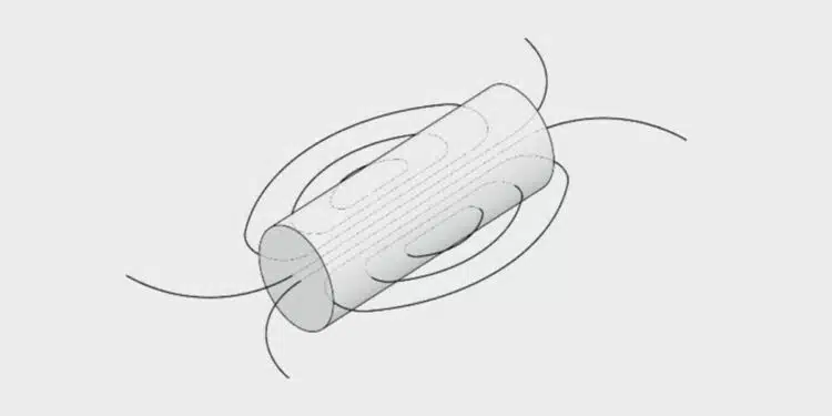
Figure 8. Field strength in air and in a ferrule

Example calculation :
Ferrite sleeve 742 700 9 on a conductor with DC current of I = 10A

Sleeve dimensions:
da = 17.5 mm; di = 9.5 mm; l = 28.5 mm

Question:
What is a field strength H1 in air and field strength H2 in ferrule (centered conductor) on Figure 8.?
Answer:
The field strengths H1 in air and H2 in the ferrule are the same size. The field strength is given by:

Related

Recent Posts

Benefits of Tantalum Powder Stress–Strain Curve Evaluation vs Conventional Wet Test

3.10.2025
4

Electrolyte Selection and Performance in Supercapacitors

3.10.2025
1

Connector PCB Design Challenges

3.10.2025
11

Researchers Demonstrated High Energy Ceramic Capacitors Stable in Wide Temperature Range

2.10.2025
14

How to Manage Supercapacitors Leakage Current and Self Discharge 

1.10.2025
19

Experimental Evaluation of Wear Failures in SMD Inductors

1.10.2025
24

Resonant Capacitors in High-Power Resonant Circuits

1.10.2025
20
a Schematic diagram of the BNT-based components constructed based on the entropy-increase strategy. b Digital photograph, cross-sectional SEM image, and EDS mappings of the MLCCs. c Unipolar P-E loops of MLCCs as a function of applied E. d Wrec and η of the MLCCs as a function of applied E. The comparison of (e) Wrec and η, (f) η and UF of the MLCCs with those of other recently reported state-of-the-art MLCCs. source: Nature Communications

Researchers Proposed Enhanced Energy Storage MLCC

1.10.2025
13

Improving SMPS Performance with Thermal Interface Material

30.9.2025
9

Polymer Tantalum Capacitors Beyond AEC-Q200 LEO Satellites

30.9.2025
39

Upcoming Events

Oct 8
11:00 - 12:00 CEST

PCB Online Shop – simply “Made in Germany” by Würth Elektronik

Oct 14
16:00 - 17:00 CEST

Smart Sensors, Smarter AI: Building Reliable Edge Systems

Oct 17
12:00 - 14:00 EDT

External Visual Inspection per MIL-STD-883 TM 2009

Oct 20
October 20 - October 23

Digital WE Days 2025 – Virtual Conference

Oct 21
October 21 @ 12:00 - October 23 @ 14:15 EDT

Space and Military Standards for Hybrids and RF Microwave Modules

View Calendar

Popular Posts

  • Buck Converter Design and Calculation

    0 shares
    Share 0 Tweet 0
  • Boost Converter Design and Calculation

    0 shares
    Share 0 Tweet 0
  • Flyback Converter Design and Calculation

    0 shares
    Share 0 Tweet 0
  • LLC Resonant Converter Design and Calculation

    0 shares
    Share 0 Tweet 0
  • SEPIC Converter Design and Calculation

    0 shares
    Share 0 Tweet 0
  • Dual Active Bridge (DAB) Topology Explained

    0 shares
    Share 0 Tweet 0
  • Ripple Current and its Effects on the Performance of Capacitors

    3 shares
    Share 3 Tweet 0
  • What is a Dielectric Constant and DF of Plastic Materials?

    4 shares
    Share 4 Tweet 0
  • MLCC and Ceramic Capacitors

    0 shares
    Share 0 Tweet 0
  • Flying Capacitors Explained

    0 shares
    Share 0 Tweet 0

Newsletter Subscription


Passive Components Blog

© EPCI - Leading Passive Components Educational and Information Site

  • Home
  • Privacy Policy
  • EPCI Membership & Advertisement
  • About

No Result
View All Result
  • Home
  • Knowledge Blog
  • Premium Suppliers

© EPCI - Leading Passive Components Educational and Information Site

This website uses cookies. By continuing to use this website you are giving consent to cookies being used. Visit our Privacy and Cookie Policy.
Go to mobile version