L.2. Equivalent Circuits and Simulation Models
Modern measuring equipment, such as the HP4195A impedance analyzer and similar instruments, allow computer-aided derivation of equivalent circuits and their optimization. Constant parameters for inductance L, capacitance C and resistance R are required for the simulation of electronic circuits. An incorrect approach in defining an equivalent circuit leads to flawed or incorrect simulation results.
Equivalent circuit parameters are in no way legally binding, exactly observable characteristics, but show the user the approximate positions of the main tolerances. The fact that this data was previously unavailable has much to do with test engineering and marketing traditions, which should be replaced by efforts towards user-friendliness in the future.
Electronic components, resistors, capacitors, inductors, conductors, approximations to ferrite materials and insulation materials can be adequately characterized with AC parameters. The condition is that their properties do not alter appreciably with different high voltage and current levels or that they are operated in the small signal range. One then speaks of linear components as opposed to non-linear components such as varistors, diodes, transistors etc.
As a consequence of spatial size in the construction of components, partial capacitances exist between each point on the surface of a conductor and every other. Conductors generate magnetic fields through current flow and have a partial inductance by virtue of the energy stored in these magnetic fields. The finite conductivity of copper, silver etc. or the conductivity of layered resistors
generated locally lead to partial resistances. Parallel conductors may also be seen as sections of high-frequency lines at high frequencies, possessing a wave resistance, signal traveling time and perhaps signal attenuation.
Reality is generally extremely complicated. If one wished to plot or even calculate a microscopically fine circuit with all partial resistances, capacitances or inductances, one would be destined for failure. Fortunately for the user, accurate equivalent circuits may easily be found for capacitors and inductors without iron or ferrite cores. Approximations of other inductive components may also be well described, whose averaged parameters are much better than unknown characteristics. Real measurement values as curves are compared to the equivalent circuit models to demonstrate the derivation of these values to the user. This particularly applies to EMC ferrites, with which interference is suppressed, but no precise circuitry is formed.
2.1 The most important types of equivalent circuits
Capacitors → series resonance
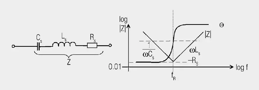
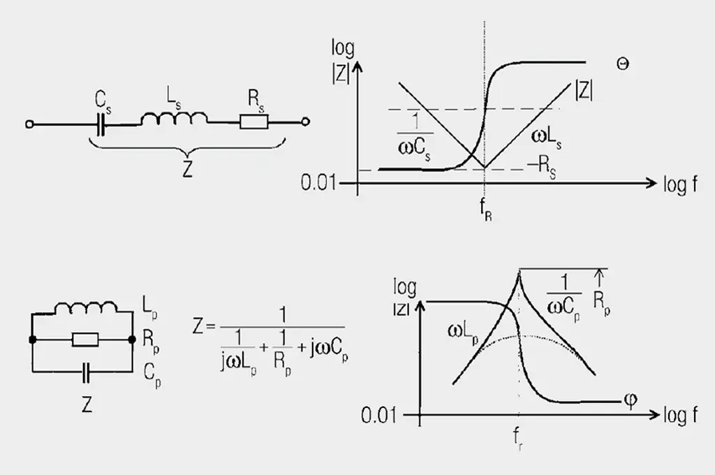
Fig. 1.39: Series resonance circuit and impedance against frequency
The ideal capacitor Cs is influenced by the lead inductance Ls (of the order of several nH) and the track resistance Rs (typ. of the order of 20 mΩ … 100 mΩ, for cold electrolyte capacitors up to 1 Ω). At low frequencies the capacitive component predominates, at the self-resonant frequency
the track resistance is measurable. Above the series resonance, the inductive component predominates, which may to some extent be influenced by having short connecting lengths. The phase curve changes from ≈ –90° to ≈ +90° in the region of resonance. The phase point 0° therefore precisely defines the point of resonant frequency, often much more precisely than is possible by means of amplitude measurement. The phase curve also serves the computer-aided determination of the equivalent circuit (1st approximation).
Inductance → parallel resonance

Fig. 1.40: Parallel circuit and impedance against frequency
The ideal inductance Lp is influenced by the unavoidable winding capacitance Cp and the assimilated Rp losses (core material, winding losses). An infinitely large parallel resistance Rp is desirable for inductors, for EMC ferrites on the other hand, a very low and broadband resistance Rp is the desired parameter. The inductance Lp plays a lesser role and is the key to transforming the resistive loss into the line.
This means that in the model, in the place of the EMC ferrite, the line is cut open and the equivalent circuit is interposed. A component is only exactly described by all three parameters L, C and R. A single parameter is insufficient, although other properties may be predicted for known configurations.
Imagine a three-dimensional coordinate system with the axes Rp, Lp, Cp; the component is a point in this space and its tolerance field is a cuboid body. Various components are located in this tolerance space as different points.

Fig. 1.41: Tolerance space
This mathematical treatment of series and parallel resonance may be summarized as follows:
Unified (normalized) resonance curves for series and parallel resonant circuits as a function of the normalized imbalance Ω in all the values of L, C and R are included. Standardized detuning unifies the parameters of quality factor and resonant frequency fRES. This makes it easier to describe the behaviour of resonant systems in their frequency range

(Δf … frequency deviation from the resonant frequency)
Series resonant circuits:

Fig. 1.42: 1 + jΩ (magnitude and phase) as a function of Ω
Parallel resonant circuits:

Fig. 1.43: 1 / 1 + jΩ (magnitude and phase) as a function of Ω
Series resonance

Parallel resonance

Resonant condition:
for series resonance:
for parallel resonance:
Normalized off-resonance:
for series resonance:
for parallel resonance:
The detuning v denotes how far the resonant circuit is detuned compared with the imposed oscillation. In short: Measure of the deviation of the (circuit) frequency from the resonant (circuit) frequency.
The normalized curves are plotted in Figures 1.42 and 1.43 for R = 1 (top magnitude, bottom phase).
Selecting the suitable operands (normalization), it is possible to illustrate all characteristics as two standard curves. They serve to provide a basic understanding, whereas in applications, the measured resonance curves are evaluated or in computer simulations, the numerical values of L, R and C.
Derivation of simple equivalent circuits
In the following examples, measurement curves derived with the HP 4195 are analyzed. It is however in principle irrelevant with which measuring device or configuration the curves are derived.
The analysis is based on fundamental theoretical modeling concepts.

Fig. 1.44: Impedance curve of a coil with 6 winding turns on a ceramic former ∅ 6 mm
Figure 1.44 shows an impedance of a small air coil of 6 mm diameter and 6 winding turns. A simple estimate of inductance from the values at 10 MHz and 100 MHz gave an L of 63.7 nH. As the phase Θ is between 85°–90°, one may assume a pure inductance and obtains from |Z| = 4 Ω at 10 MHz and |Z| = 40 Ω at 100 MHz.

The analyzer measures L = 58 nH as a result of its more accurately stored values than those displayed. Two curves are just distinguishable in Figure 1.44, a thick measurement curve and one, which the analyzer plotted as the result of its equivalent circuit measurement. It actually includes an equivalent circuit calculator. It calculates the equivalent circuit plotted in Figure 1.44 and writes the calculated values of |Z| and Θ alongside the measurement curve. Without a computer, one would have to be content with just a rough calculation.
Multi-dimensional measures are required in EMC matters; precision is not of paramount importance.

Fig. 1.45: Impedance curve of a 10 nF ceramic capacitor with approx. 5 mm long connecting legs
Figure 1.45 shows the impedance curve of a ceramic disc capacitor of 10 nF capacitance rating with approx. 5 mm long connecting legs. By reading the measurement curves and calculation, C = 11.37 nF and L = 9.55 nH could be found. From the |Z| curve at Θ = –90°, the capacitance

and at Θ = + 90° the inductive component

can be calculated.
|Z|200 kHz = 70 Ω, |Z|4 MHz ≈ 3.5 Ω, C = 11.37 nF, |Z|40 MHz ≈ 2 Ω,
|Z|200 MHz = 12 Ω and L = 9.55 nH.
The series resistance was 33.8 mΩ according to the measurement. With the correctly selected equivalent circuit (Figure 1.45), the analyzer measured R = 33.7 mΩ, C = 11.2 nF and L = 9 nH and the its coinciding curve showed that there were no further parasitic equivalent circuit parameters of any significance. Whereas the coil in Figure 1.45 is still useful at 200 MHz, the capacitor
is only applicable up to 30 MHz.
One recognizes from this, how terribly important it is to consider line inductances in association with blocking processes. An example in Figure 1.46 illustrates this.

Fig. 1.46: The effect of a triangular pulse, as arises during the switching edge in logic circuits, on a capacitor with line inductances
If a triangular pulse reaches a “naked” capacitor without inductance, a voltage reduction of 25 mV occurs in 10 ns with rounded falling edge. The line inductance of 9 nH alone adds a bipolar pulse with steep edge of ±90 mV, an effect that everyone who has looked at their power supply line with an oscilloscope has observed. It is of little use to substitute 10 nF with 1 μF; if the inductance remains, the noise voltage remains. The pure change in charge in a 10 nF capacitor due to the triangular pulse leads to a change in voltage ΔU at the capacitor.

The current edges ΔI/Δt at just 9 nH generate a bipolar voltage shift of

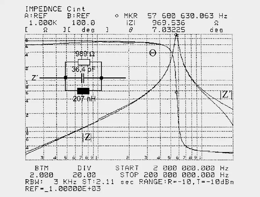
Fig. 1.47: Impedance curve and equivalent circuit of a resonant circuit
As an example, Figure 1.47 shows a resonance circuit comprising coil and capacitor in parallel with a 1 kΩ resistor. The analyzer with the structure A selected wins the equivalent circuit hands down. Other structures give rise to poor or worthless approximations. The analyzer primarily attempts to approach the phase curve. One can manually improve the parameters and arrive at new approximations.
The inductance may be determined from the measurement curve in this case. Capacitance may only be found to a limited extent. |Z|3 MHz = 4 Ω, |Z|57.6 MHz = 969 Ω, |Z|200 MHz= 24 Ω, Lp = 207 nH, Rp = 989 Ω, Cp = 36.4 pF.
The resonance condition then helps:

The analyzer results confirm the calculated values.
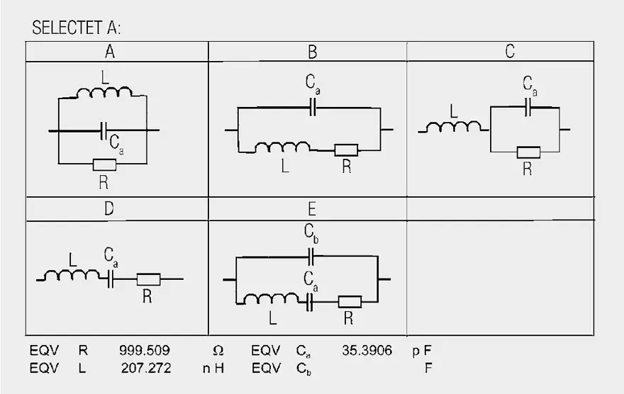
Fig. 1.48: Equivalent circuit types from HP4195A

Fig. 1.49: Impedance curves for the parallel connection of two dissimilar capacitors (Legend of effective HF blocking)
Figure 1.49 shows the impedance curve for the parallel connection of 2 dissimilar capacitors. The larger 150 nF capacitor was supplemented with a small 150 pF capacitor to improve HF blocking. It should “balance” the disadvantage of the capacitor’s longer line to the load. The result is a resonant peak at 61.57 MHz with a Z of 590 Ω (with no load attached). Every steep pulse edge would definitely cause a long damped oscillation and the significantly reduce the usefulness of blocking.
Derivation of the equivalent circuit from the |Z| curves takes place in several steps. The phase curve Q signalizes a capacitance of up to 2 MHz (zone I). The series resonance at 2 MHz is a consequence of the approx. 4 cm long connection legs of the 150 pF capacitor. The circuit is inductive in zone II to generate a parallel resonance with 590 Ω at 60 MHz, where one can no longer
speak of blocking. From 30 MHZ–100 MHz (zone III) the impedance is greater than 100 Ω and is extremely detrimental for internal signal coupling. The 150 pF capacitor starts to play a role beyond the parallel resonance and affects a series resonance at 154 MHz. The phase curve Q is observed in zone IV.
Calculated values are
in zone I |Z|600 kHz = 2 Ω ∩ 133 nF,
in zone II |Z|20 MHz = 6.5 Ω ∩ 52 nH,
in zone III resonance 61.6 MHz Cb = 1/ω2 · L = 128.6 pF,
in zone IV resonance 154.6 MHz L – 1/ω2 · Cb = 8.25 nH
The equivalent circuit is obtained
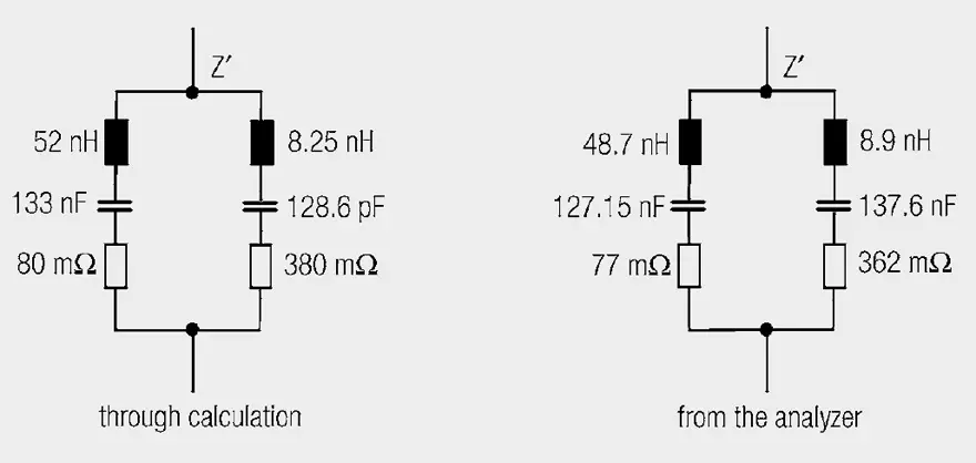
Fig. 1.50: Equivalent circuit of two parallel connected capacitors
ABC of CLR: Chapter L Inductors
Equivalent Circuits and Simulation Models – Circuit Types
EPCI licensed content by: Würth Elektronik eiSos, Trilogy of Magnetics, handbook printouts can be ordered here.

This page content is licensed under a Creative Commons Attribution-ShareAlike 4.0 International License.