Passive Components Blog
No Result
View All Result
  • Home
  • NewsFilter
    • All
    • Aerospace & Defence
    • Antenna
    • Applications
    • Automotive
    • Capacitors
    • Circuit Protection Devices
    • electro-mechanical news
    • Filters
    • Fuses
    • Inductors
    • Industrial
    • Integrated Passives
    • inter-connect news
    • Market & Supply Chain
    • Market Insights
    • Medical
    • Modelling and Simulation
    • New Materials & Supply
    • New Technologies
    • Non-linear Passives
    • Oscillators
    • Passive Sensors News
    • Resistors
    • RF & Microwave
    • Telecommunication
    • Weekly Digest

    Exxelia Releases Updated Microwave Materials and Frequency Tuning Catalogues

    Coilcraft Unveils Molded Power Inductors for High‑Current VRMs

    Murata Automotive MLCCs Push Capacitance Limits for ADAS and Power Lines

    TDK Releases Ultra‑small EMI Noise Suppression Filters

    Littelfuse Presents Ultra-Miniature Half-Pitch SMT DIP Switches

    SCHURTER Releases Compact SMT DIP Switches

    TDK and Nippon Chemical Launch Joint Venture for MLCC Materials

    Wk 14 Electronics Supply Chain Digest

    Bourns Releases Compact High Current Shielded Power Inductors

    Trending Tags

    • Ripple Current
    • RF
    • Leakage Current
    • Tantalum vs Ceramic
    • Snubber
    • Low ESR
    • Feedthrough
    • Derating
    • Dielectric Constant
    • New Products
    • Market Reports
  • VideoFilter
    • All
    • Antenna videos
    • Capacitor videos
    • Circuit Protection Video
    • Filter videos
    • Fuse videos
    • Inductor videos
    • Inter-Connect Video
    • Non-linear passives videos
    • Oscillator videos
    • Passive sensors videos
    • Resistor videos

    Transformer-Based Power-Line Harvester Magnetic Design

    Thermal Modeling of Magnetics

    Standard vs Planar LLC transformers Comparison for Battery Chargers

    How Modern Tools Model Magnetic Components for Power Electronics

    Advanced Loss Modeling for Planar Magnetics in the Frenetic Planar Tool

    2026 Power Magnetics Design Trends: Flyback, DAB and Planar

    Enabling Software‑Defined Vehicle Architectures: Automotive Ethernet and Zonal Smart Power

    Calculating Resistance Value of a Flyback RC Snubber 

    One‑Pulse Characterization of Nonlinear Power Inductors

    Trending Tags

    • Capacitors explained
    • Inductors explained
    • Resistors explained
    • Filters explained
    • Application Video Guidelines
    • EMC
    • New Products
    • Ripple Current
    • Simulation
    • Tantalum vs Ceramic
  • Knowledge Blog
  • DossiersNew
  • Suppliers
    • Who is Who
  • PCNS
    • PCNS 2025
    • PCNS 2023
    • PCNS 2021
    • PCNS 2019
    • PCNS 2017
  • Events
No Result
View All Result
Passive Components Blog
No Result
View All Result

Low Inductance Ceramic Capacitors for High-Speed Decoupling

15.2.2023
Reading Time: 9 mins read
A A

This blog article written by Robert Lu, KYOCERA-AVX Corporation introduces low ESL inductance ceramic capacitors for high-speed decoupling applications.

Introduction of Decoupling Capacitors

Modern integrated circuits (IC’s) consume power at rapidly varying rates due to the density of circuits on-board and the extreme speed at which they can operate.

RelatedPosts

Kyocera Releases 30fs Jitter Differential Clock Oscillator

KYOCERA AVX Extends Ultra‑Broadband RF Capacitor Series

Kyocera Offers Small SAW Filters for IoT RF Modules

Power supplies are required to respond to these changes in load current while maintaining a constant operating voltage.

This task is becoming increasingly difficult as the complexity of power distribution networks grows and printed circuit board (PCB) design requires optimization for parasitic inductance and capacitance.

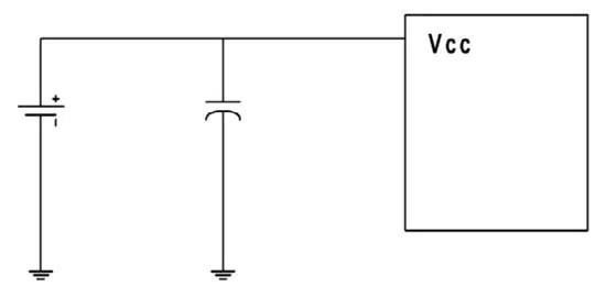
Therefore, any power supply performance slack must be absorbed by the all-too-common decoupling capacitor. As shown in Figure 1, a decoupling capacitor is simply an additional parallel capacitance that provides a stable voltage and source of current when the main power supply is unable to adjust quickly enough or is too far away to properly function.

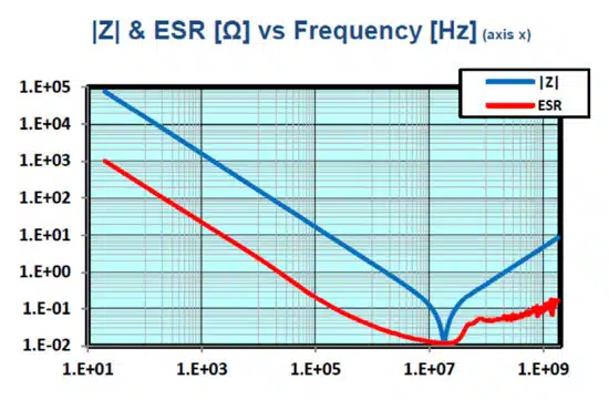
As the operating frequency of IC’s continues to rise, these parasitic elements become of greater significance when considering a capacitor for decoupling purposes. As the frequency increases, the AC impedance of the equivalent circuit model drops, and the capacitive component loses dominance.

Figure 1 – Power supply, decoupling capacitor, and integrated circuit
Figure 2 – Realistic capacitor equivalent circuit model
Figure 3 – Capacitor frequency response example

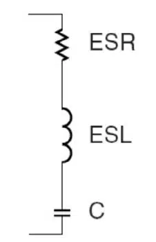
Unfortunately, the idealized notion of a capacitor as an instantaneously available energy source is far from the truth at higher frequencies. As shown in Figure 2, physical capacitors present a parasitic equivalent series inductance (ESL) and equivalent series resistance (ESR) in addition to the bulk capacitance.

At a certain point, the inductive and capacitive components are equivalent, and the inductance becomes dominant above this frequency. This crossover point is known as the self-resonant frequency and is visible in Figure 3, showing the frequency response of 100 nF, 0603 ceramic capacitors.

At low frequencies, decoupling performance may be as simple as just adding an adequately sized multi-layer ceramic capacitor (MLCC) as close as possible to the target IC. However, achieving decoupling performance at high frequencies is a much more complex and nuanced problem.

Decoupling for High-Performance Circuits

For high-performance circuits, proper decoupling requires the designer to consider the frequency demands of the load, the frequency response of the capacitor, and the overall layout and routing of the PCB.

It is also common to discover that a single capacitor is inadequate, and instead, an array of capacitors of different values and constructions must be employed. Tantalum capacitor or aluminum electrolytic devices are preferable for low frequency and high capacitance. For high frequency and low ESL, multiple parallel ceramics are typically used.

For n discrete devices in parallel, the capacitance is increased to nC, the inductance is decreased to ESL/n, and the resistance is decreased to ESR/n. The self-resonance frequency remains the same as the original single capacitor.

The positioning of these capacitors is also of utmost importance. The term “decoupling diameter” is often used to describe the maximum distance from the target IC that a particular capacitor can serve as an effective decoupling component. When considering PCB trace length and inductance, the farther away from the target IC a capacitor is, the lower the frequency it can effectively respond to.

Figure 4 – Intel CPU with low ESL decoupling array

As such, the decoupling diameter of a particular capacitor is conceptually visualized as the phase difference between the power supply noise pulses and the capacitor’s offsetting currents. Based on experience, the distance of decoupling diameter should be controlled within λ/40 to λ/50.

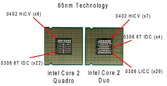
The high-frequency capacitor array should be placed physically close to the IC, considering decoupling diameter and MLCC bulk capacitance. An example is shown in Figure 4, where a complex capacitor array is included on the actual CPU package for decoupling high-frequency power draws.

In addition to placement, the actual routing and via hole design should be considered to minimize inductance. The inductance of a through-hole is shown in the equation below:

Equation 1 – Inductance of a PCB through-hole

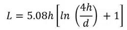
L: the inductance of through-hole, unit nH
h: the length of the through-hole, unit inch
d: the diameter of the through-hole, unit inch

Figure 5 – Via placement for low inductance

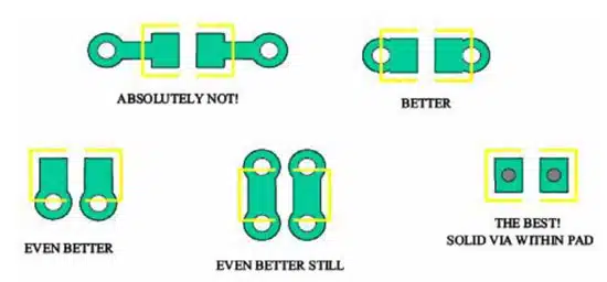
Figure 5 shows that the actual via placement relative to the PCB trace also affects inductance. The optimal configuration is to place the via within the actual capacitor pad and eliminate any length of trace all together.

While optimization of PCB layout and capacitor array values is important, the choice of the actual capacitor construction can yield the greatest performance benefit. Unfortunately, this requires a complex trade-off analysis concerning size, cost, performance, and availability. Several low ESL capacitor families are available from KYOCERA AVX, including low inductance chip, feedthrough, interdigitated, and land grid array.

Low Inductance Capacitor Families

Low Inductance Chip Capacitors

A Low Inductance Chip Capacitor (LICC), sometimes referred to as Reverse Geometry Capacitor (RGC), has its terminations on the longer sides of its rectangular shape. This difference is shown in Figure 6. By reducing the distance between the terminations, the size of the current loop is reduced.

Since the size of the current loop is the primary driver of inductance, an 0306 with a smaller current loop has significantly lower ESL than a 0603. The reduction in ESL varies by EIA size. However, ESL is typically reduced by 60% or more with an LICC versus a standard MLCC.

Figure 6 – Traditional MLCC (left) and reverse geometry for low ESL capacitors (right)

Feedthrough Capacitors

Figure 7 – Feedthrough capacitor internal structure and equivalent circuit

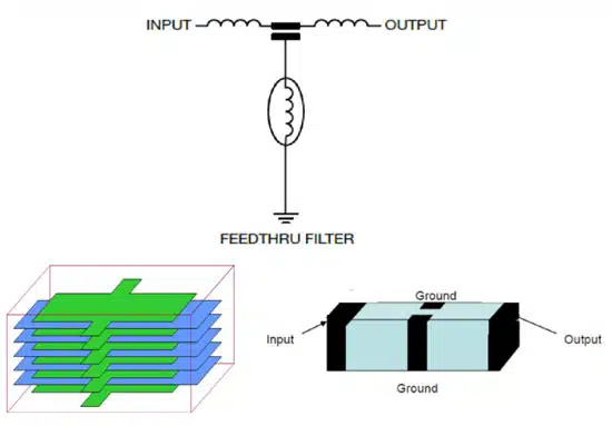
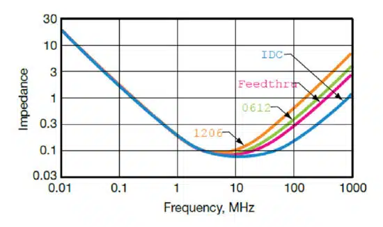
Also known as three-terminal capacitors, feedthrough capacitors are constructed so that the input and output inductance cancel each other out, and a dedicated low inductance path to ground is guaranteed. Figure 7 shows a common feedthrough structure and the equivalent circuit model. Figure 8 presents the frequency response of a feedthrough device compared to several other capacitor structures. The inductance at high frequency is reduced while only marginally affecting the PCB complexity and area.

Figure 8 – Feedthrough capacitor frequency response compared to 1206, 0612, and IDC devices

IDC Interdigitated Capacitors

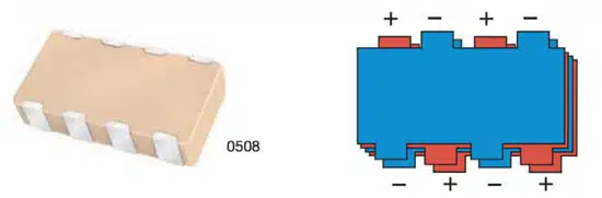
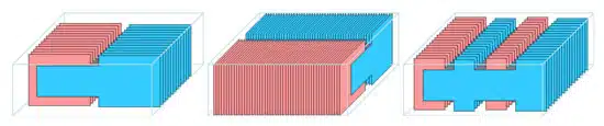
Interdigitated capacitors (IDC) are a specialized capacitor family used to replace a capacitor array for package level and board level decoupling applications. These capacitors offer the lowest ESL while simultaneously reducing PCB space requirements compared to an equivalent MLCC array, as shown in Figure 9.

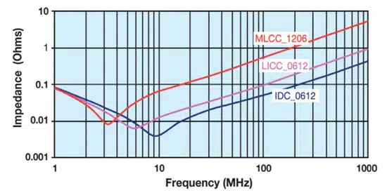
A representative frequency response is shown in Figure 10, where the IDC exhibits a lower ESL compared to an MLCC by more than an order of magnitude.

Figure 9 – IDC Interdigitated capacitor structure
Figure 10 – IDC frequency response compared to LICC and MLCC

LGA Land Grid Array Capacitors

Figure 11 – LGA capacitor internal structure

Land grid array (LGA) capacitors offer comparable low ESL performance to IDC devices but use an advanced manufacturing process to orient the inner terminals vertically, thus reducing the number of PCB terminations.

As a result, PCB area requirements are minimized, and overall capacitor density can be increased. The internal structure of the LGA device is shown in Figure 11.

Low ESL Capacitors for High-Frequency Decoupling

Designing a power delivery network for high-performance IC’s requires careful layout, selection, and routing of the decoupling capacitors.

Traditional electrolytics and MLCCs can be used for low to mid-frequency bands. For high frequencies, engineers must employ more advanced techniques and devices.

KYOCERA AVX offers a variety of low ESL capacitors for high-frequency decoupling of board-level and package-level circuits.

Related

Recent Posts

Murata Automotive MLCCs Push Capacitance Limits for ADAS and Power Lines

8.4.2026
23

TDK and Nippon Chemical Launch Joint Venture for MLCC Materials

7.4.2026
29

March 2026 Interconnect, Passives and Electromechanical Components Market Insights

2.4.2026
79

APEC 2026 Power Electronics Trends and Implications for Passive Components

1.4.2026
97

Hydra Enhances Film Capacitor Robustness by Novel Gel Filler

1.4.2026
30

Würth Elektronik Releases Heat Sinks for TO and IC packages

31.3.2026
26

Indias ECMS Wave Brings New Capacity For Passive Components Manufacturing in India

31.3.2026
52

Samsung Introduces 35V MLCCs Flying Capacitors for USB PD Fast Charging

27.3.2026
36

New J‑STD‑075B Standard Elevates Process Sensitivity Classification for Passive and Solid-State Components

27.3.2026
58

Upcoming Events

Apr 21
16:00 - 17:00 CEST

Heatsink Solutions: Thermal Management in electronic devices

May 5
16:00 - 17:00 CEST

Understanding and Selecting Capacitors – Fundamentals, Technologies and Latest Trends

May 19
16:00 - 17:00 CEST

Designing Qi2 Wireless Power Systems: Practical Development and EMC Optimization

View Calendar

Popular Posts

  • Buck Converter Design and Calculation

    0 shares
    Share 0 Tweet 0
  • Boost Converter Design and Calculation

    0 shares
    Share 0 Tweet 0
  • Flyback Converter Design and Calculation

    0 shares
    Share 0 Tweet 0
  • LLC Resonant Converter Design and Calculation

    0 shares
    Share 0 Tweet 0
  • Dual Active Bridge (DAB) Topology

    0 shares
    Share 0 Tweet 0
  • MLCC and Ceramic Capacitors

    0 shares
    Share 0 Tweet 0
  • Capacitor Charging and Discharging

    0 shares
    Share 0 Tweet 0
  • Plastic Materials Dielectric Constant and DF

    4 shares
    Share 4 Tweet 0
  • Ripple Current and its Effects on the Performance of Capacitors

    3 shares
    Share 3 Tweet 0
  • MLCC Case Sizes Standards Explained

    0 shares
    Share 0 Tweet 0

Newsletter Subscription


Passive Components Blog

© EPCI - Leading Passive Components Educational and Information Site

  • Home
  • Privacy Policy
  • EPCI Membership & Advertisement
  • About

No Result
View All Result
  • Home
  • Knowledge Blog
  • PCNS

© EPCI - Leading Passive Components Educational and Information Site

This website uses cookies. By continuing to use this website you are giving consent to cookies being used. Visit our Privacy and Cookie Policy.
Go to mobile version