


The most common large size film capacitors are based on PP and PET dielectrics, but is there any advantage to consider PPS, PEN or acrylic film capacitors for a small chip size and can they compete with MLCC capacitors? For anyone seeking a capacitor coming in a small case size, with a low-to-high voltage range, high precision and stable capacitance it may worth to look at SMD chip type miniature film capacitors and its advantages in number of applications.
The case of chip type film capacitors and some of their basic features, look pretty much like MLCCs. So, what’s the difference between the two technologies? What are the advantages chip type film capacitors have?
Let’s make a quick comparison to find the answer.
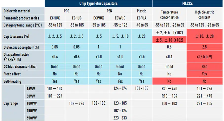
compared with MLCCs, chip type film capacitors have following advantages in terms of electric characteristics:
- High preciseness: a tight capacitance range down to ±2%
- Wide voltage range up to 630VDC
- Low dielectric absorption down to 0.05%
- Better DC bias characteristics
- No piezoelectric effect
- Self-healing ability
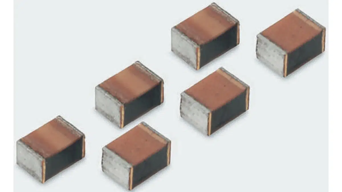
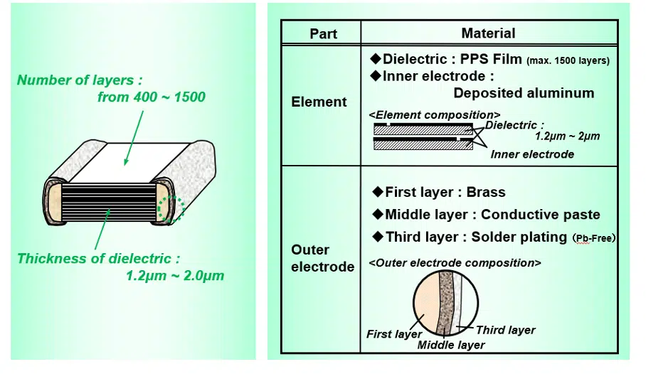
PPS SMD Film Capacitors
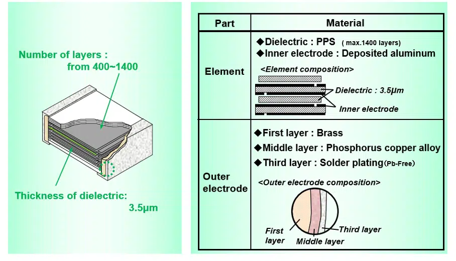
These capacitors are made using stacked metallized PPS film as a dielectric with simple mold-less construction. The construction may be slightly different for a lower voltage range such as 16VDC-50VDC (See Fig. 2.) and higher voltage chips around 100VDC (see Fig.3.).
Features
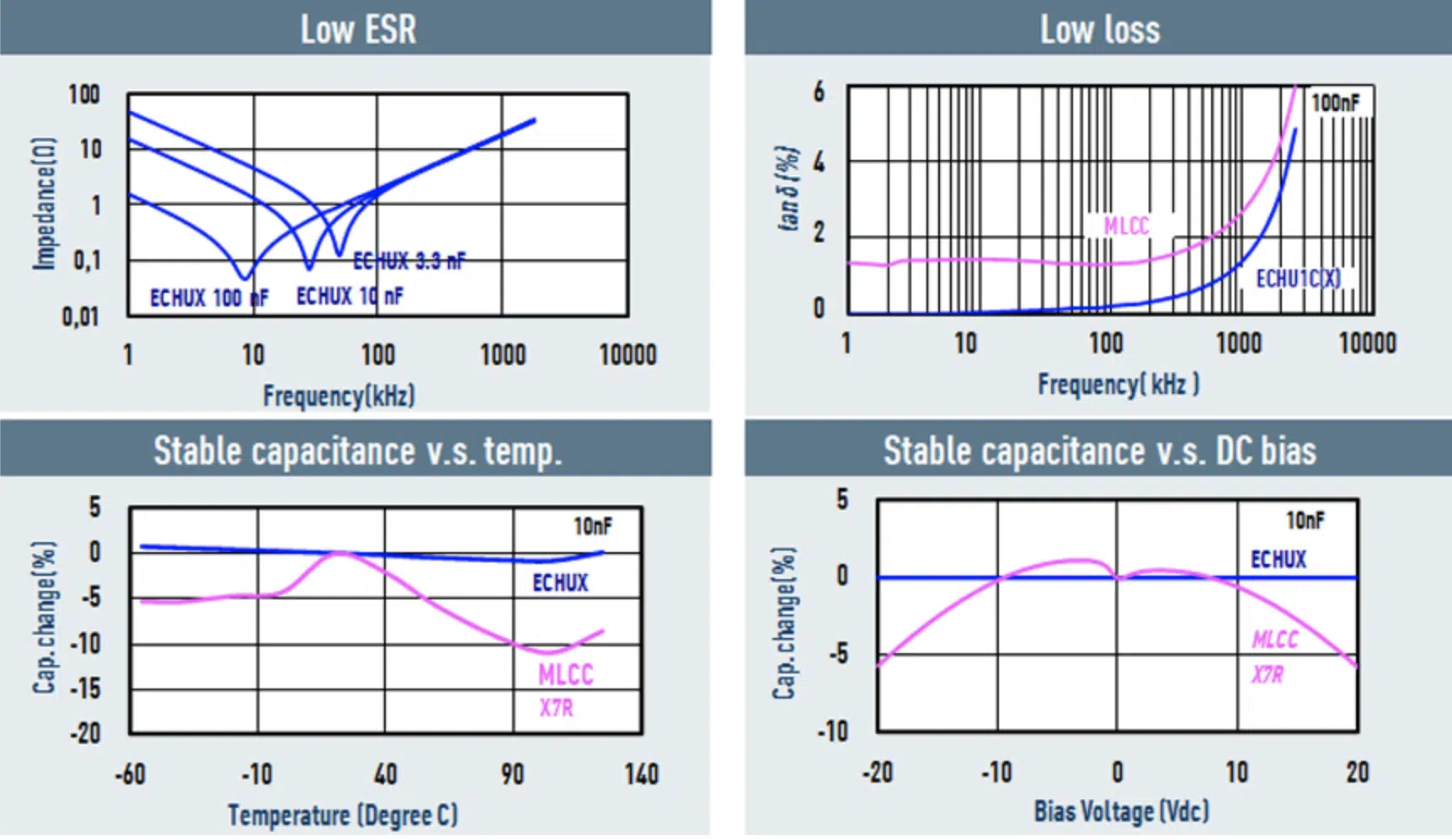
- excellent electric characteristics
- low ESR, low DF
- stable capacitance against temperature and DC bias
- down to 1.6mm x0.8mm footprint
- tight capacitance tolerance of ±2% & ±5%
- capacitance up to 220nF
- 16VDC to 100VDC voltage ratings
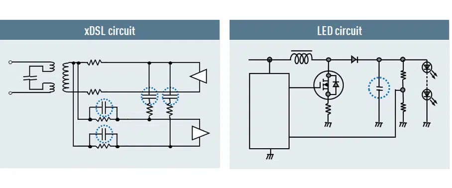
Applications
The excellent electrical parameters stability makes PPS film chip capacitors as the most suitable solution for filtering in xDSL circuit of class D amplifiers for speakers, smartphones and wireless communication etc., as well as for LED circuits.
The key benefit of PPS film capacitors in these applications is a very fast lock-up time and it doesn’t show a piezoelectric effect as MLCCs do, which makes it a perfect solution for PLL (phase locked loop) circuit in applications such as smart phones, wireless communication and Bluetooth® devices etc. See figure 6.

Acrylic Plastic SMD Film Capacitors
These type of film capacitors utilize stacked metallized acrylic plastic film as dielectric and inner electrode with simple mold-less construction.
Features
- wide capacitance range up to 1.0μF
- small case size (3.2mm x2.5mm footprint for 1.0μF)
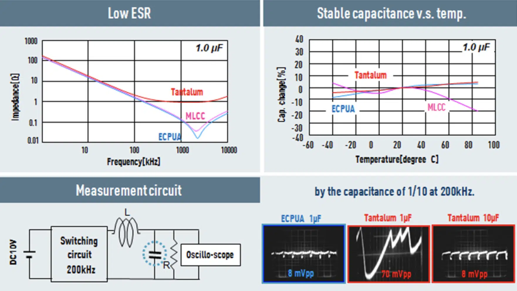
- excellent electric characteristics
- low ESR, low DF
- stable capacitance over temperature
- outstanding performance for noise reduction in measurement circuits
- ultra-low distortion characteristics ideal for coupling in audio circuits


PEN SMD Film Capacitors
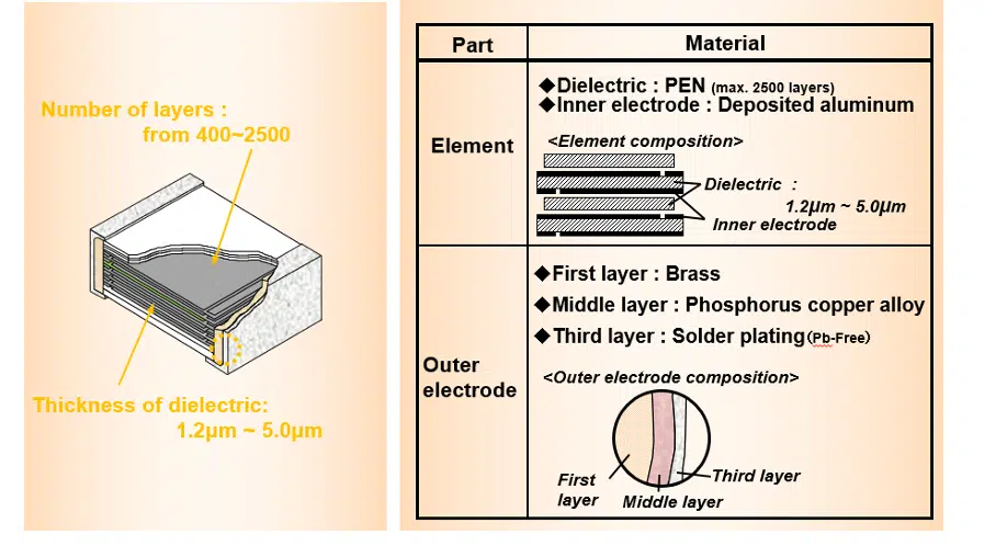
This type of capacitors is based on stacked metallized PEN film as dielectric with simple mold-less construction.
Features
- small case size
- wide voltage range up to 630VDC
- stable capacitance and ESR characteristics against bias and temperature
- ideal for DC blocking in xDSL circuit, as well as integration for EL lamp driver
PPS vs Acrylic vs PEN SMD Film Capacitors Comparison
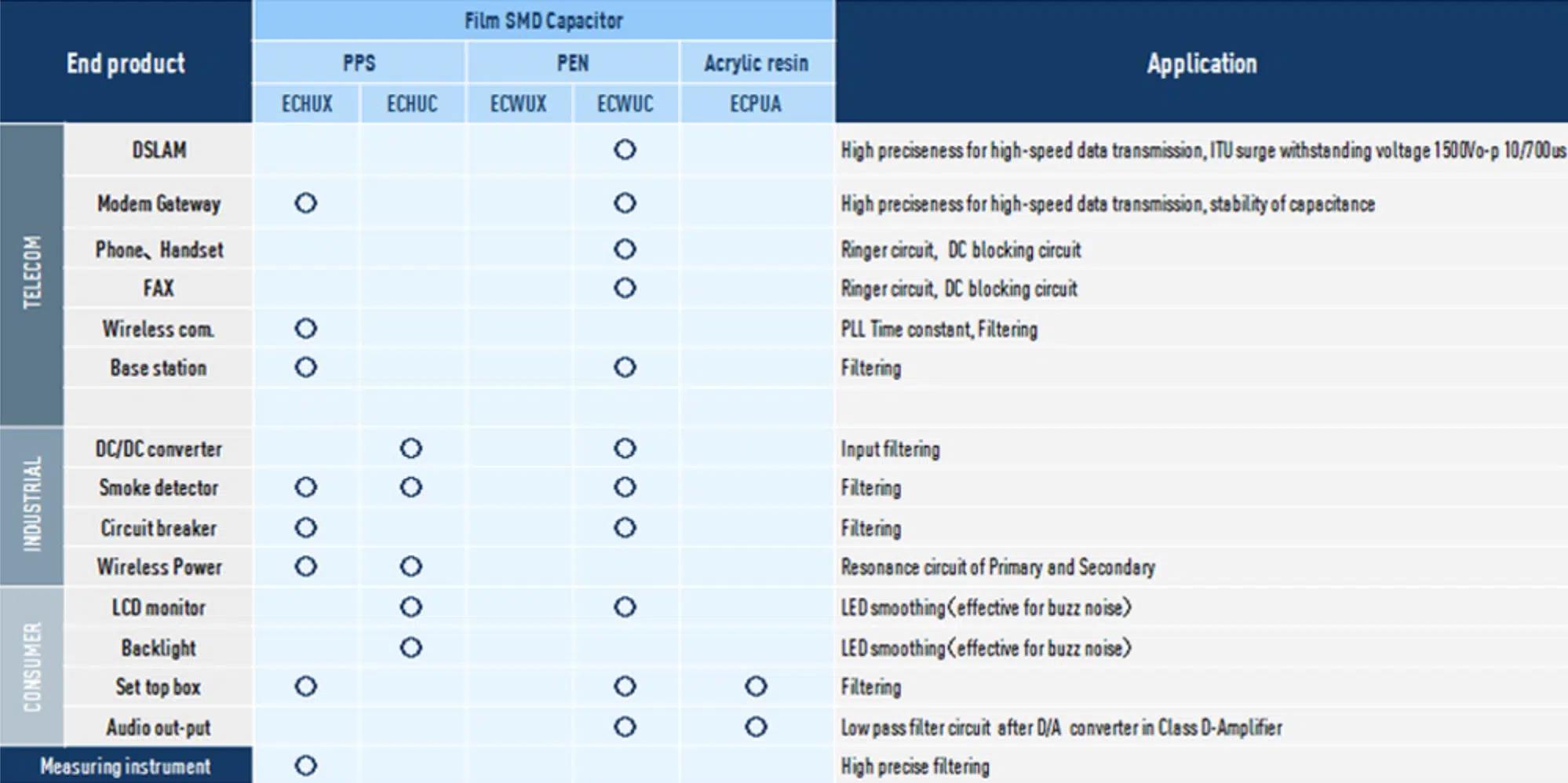
Let’s summarize what kind of typical applications will benefit from the small high precision, high performance chip type PPS, Acrylic and PEN film capacitors offer.


