Passive Components Blog
No Result
View All Result
  • Home
  • NewsFilter
    • All
    • Aerospace & Defence
    • Antenna
    • Applications
    • Automotive
    • Capacitors
    • Circuit Protection Devices
    • electro-mechanical news
    • Filters
    • Fuses
    • Inductors
    • Industrial
    • Integrated Passives
    • inter-connect news
    • Market & Supply Chain
    • Market Insights
    • Medical
    • Modelling and Simulation
    • New Materials & Supply
    • New Technologies
    • Non-linear Passives
    • Oscillators
    • Passive Sensors News
    • Resistors
    • RF & Microwave
    • Telecommunication
    • Weekly Digest

    KYOCERA AVX Releases T1 Industrial Single-Pair Ethernet Connectors

    Würth Elektronik Opens Branch in South Africa

    Comparative display of a grain size and domain structure; b free energy; c P-E loops after high-entropy ceramics (HECs) and PGS design. source: Nature Communications  ISSN 2041-1723

    Researchers Propose Novel MLCC Dielectric Design to Increase Energy Storage Capacity

    Stackpole Unveils 1W High Power Density Current Sense Chip Resistor

    Bourns Releases New 150C Shielded Power Inductors

    iNRCORE Releases New Range of 1KW HiRel Planar Transformers

    Murata Releases In-vehicle Compact Crystal in 2016 Size

    Vishay Releases Industrial-Grade 3/8 Square Single-Turn Cermet Trimmer

    July 2025 Interconnect, Passives and Electromechanical Components Market Insights

    Trending Tags

    • Ripple Current
    • RF
    • Leakage Current
    • Tantalum vs Ceramic
    • Snubber
    • Low ESR
    • Feedthrough
    • Derating
    • Dielectric Constant
    • New Products
    • Market Reports
  • VideoFilter
    • All
    • Antenna videos
    • Capacitor videos
    • Circuit Protection Video
    • Filter videos
    • Fuse videos
    • Inductor videos
    • Inter-Connect Video
    • Non-linear passives videos
    • Oscillator videos
    • Passive sensors videos
    • Resistor videos

    Understanding Inductor Dot Markings and Their Application in LTspice

    Accelerating Full Bridge LLC Resonant Converter Design with Frenetic AI

    Understanding Switched Capacitor Converters

    Coupled Inductors Circuit Model and Examples of its Applications

    Inductor Resonances and its Impact to EMI

    Highly Reliable Flex Rigid PCBs, Würth Elektronik Webinar

    Causes of Oscillations in Flyback Converters

    How to design a 60W Flyback Transformer

    Modeling and Simulation of Leakage Inductance

    Trending Tags

    • Capacitors explained
    • Inductors explained
    • Resistors explained
    • Filters explained
    • Application Video Guidelines
    • EMC
    • New Products
    • Ripple Current
    • Simulation
    • Tantalum vs Ceramic
  • Knowledge Blog
  • Suppliers
    • Who is Who
  • Events
No Result
View All Result
Passive Components Blog
No Result
View All Result

MLCC capacitors for RF and microwave applications

20.12.2019
Reading Time: 5 mins read
A A

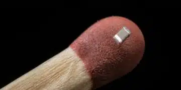
Capacitors have numerous applications in today’s RF and microwave systems. The performance characteristics of these components are greatly dependent on the frequency. Unlike typical uses, RF and microwave applications demand capacitors that are specially optimized to operate at high frequencies. The impressive characteristics of today’s multilayer ceramic (MLCC) capacitors make them an ideal choice for various RF and microwave applications. In this article, we will explore some of the key considerations when selecting capacitors for these applications.

Uses of capacitors in RF and microwave circuits

RelatedPosts

KYOCERA AVX Releases T1 Industrial Single-Pair Ethernet Connectors

Würth Elektronik Opens Branch in South Africa

Researchers Propose Novel MLCC Dielectric Design to Increase Energy Storage Capacity

Capacitors have a broad array of applications in high frequency circuits and systems. Some of the most common applications include filtering, bypassing, impedance matching, DC blocking, tuning and timing applications. These circuits can be found in a broad array of high frequency systems including the following:

  • Wireless broadcast equipment
  • Satellite communication equipment
  • Matching networks
  • Voltage controlled oscillators
  • Wireless LAN devices
  • RF power amplifiers
  • RF modules and filters
  • Broadband test equipment
  • Optoelectronics/high-speed systems

As the number of electronic systems operating at high frequencies increase (5G, automotive radars, High speed satellites etc.), so is the demand for capacitive devices that are optimized to operate at RF and microwave frequencies. Consequently, there has been a significant improvement in the design and construction of capacitors, especially ceramic capacitors.

The performance characteristics of capacitors are significantly affected by conditions at which a component is used. Variations in frequency and/or temperature are known to significantly impact the overall performance of capacitors. For RF and microwave applications, capacitors with the following characteristics are required:

  • Extremely low equivalent series resistance (ESR)
  • Ultra high self-resonance characteristics
  • Ultra high Q
  • High thermal stability
  • Zero or negligible piezoelectric noise
  • Zero or negligible decay in capacitance with timeZero or negligible variation in capacitance with applied voltage
  • Zero or negligible variation in capacitance with temperature
  • Good solderability

Key capacitor considerations for RF and microwave applications

For typical applications, some of the main performance characteristics to consider when choosing a capacitor include the voltage characteristics, temperature characteristics, termination and capacitance value. As the frequency of operation increases, there are other factors that become critical and must be considered when selecting a component.

To start with, at RF and microwave frequencies, it is imperative to consider the equivalent series resistance (ESR) of a component. RF and microwave applications demand capacitors with low ESR. The power loss in a circuit is greatly determined by the ESR of the capacitive components used. To minimize power loss in high frequency circuits, it is crucial to use components with extremely low ESR.

When choosing a capacitor for a high frequency application, it is also important to consider the attenuation properties of a component. A component with poor attenuation characteristics can significantly degrade a signal thereby affecting the overall performance of a circuit. The attenuation characteristics of a capacitor are commonly described in terms of self-resonant frequency.

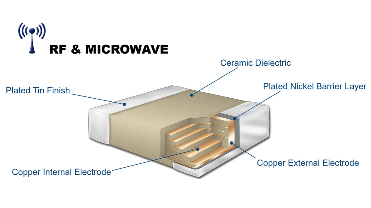
The performance characteristics of a capacitor are greatly determined by the materials used as well as the construction technology used. In the case of MLCCs, the materials used affect both the equivalent series resistance and the self-resonant frequency.

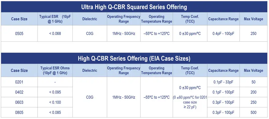
The frequency-sensitive properties of MLCCs vary depending on the class of materials used for their construction. Class I ceramic materials, for example NPO and COG, yield capacitors with very low ESR. Even at high frequencies, the ESR of these components is relatively low. On the flip side, these components have a relatively high self-resonant frequency at RF and microwave frequencies. See Tab 1. below with an example of RF & Microwave C0G MLCC specifications.

Tab.1. Example of RF & Microwave C0G MLCC specification; source: Kemet Electronics Q-CBR series datasheet

In comparison, Class II ceramic materials, for example X7R, yield MLCCs with slightly different performance characteristics. At high frequencies, Class II ceramic capacitors exhibit relatively high ESR and relatively low SRF.

At RF and microwave frequencies, the ESR of Class I ceramic capacitors is lower than that of Class II ceramic capacitors while the SRF of Class I ceramic capacitors is higher than that of Class II capacitors. In most high frequency applications, the very low ESR of Class I ceramic capacitors make them better choice.

Although the ceramic formulation is arguably the main factor that determines the performance of ceramic capacitors, it is important to note that the overall performance of a component is determined by a matrix of factors. For special applications that demand optimum performance, it is crucially important to ensure that the design of a component is fully optimized.

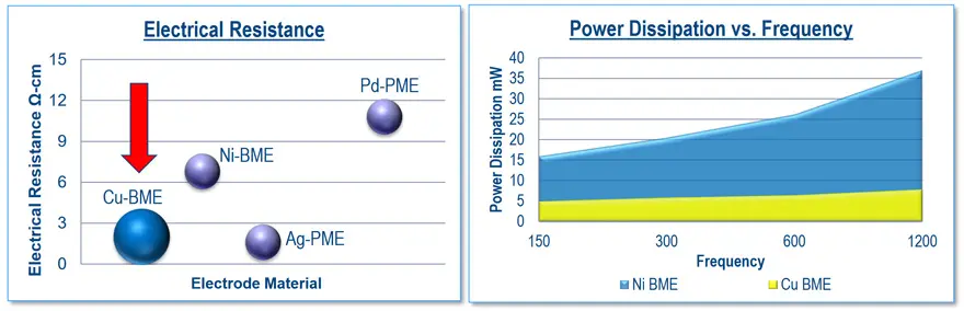
Electrodes play a critical role in the operation of capacitors. In ordinary capacitors, copper and nickel (BME) are commonly used as electrodes. At high frequencies, capacitors that have nickel electrodes exhibit unacceptably high losses. To overcome this limitation, materials with better conductivity characteristics are developed.

Traditionally compared to BME electroides, precious metals (PME) have had better conductivity and were commonly used as electrodes in capacitors for applications that demand low losses. The precious metals that are commonly used for this purpose include palladium, silver, and platinum. Nevertheless, the high cost of PME lead to the development of new generation of BME electrodes based on copper exhibiting very high conductivity and low losses. See Fig.1 below.

Electrical resistance and power dissipation comparison of BME and PME RF MLCCs; source: Kemet Electronics

When selecting an electrode material for a high frequency capacitor, it is important to consider how it impacts various performance characteristics, especially insertion loss and self-resonant frequency.

Conclusion

Capacitors have a broad array of uses in RF amplifiers, satellite communications equipment, filter systems, wireless broadcast systems, and other RF and microwave systems. Unlike typical capacitor uses, these applications demand components that are specially designed to perform optimally at high frequencies. The attenuation and the equivalent series resistance of a capacitor are critical factors when designing a high frequency system. Capacitors for use in RF and microwave systems are specially designed and constructed to deliver the required performance characteristics. The impressive properties of multilayer ceramic capacitors make them a suitable choice for various RF and microwave applications.

modified by EPCI from source:

Related

Source: Capacitor Faks blog

Recent Posts

Comparative display of a grain size and domain structure; b free energy; c P-E loops after high-entropy ceramics (HECs) and PGS design. source: Nature Communications  ISSN 2041-1723

Researchers Propose Novel MLCC Dielectric Design to Increase Energy Storage Capacity

24.7.2025
10

July 2025 Interconnect, Passives and Electromechanical Components Market Insights

23.7.2025
23

Samsung Electro-Mechanics Focuses MLCCs on AI servers and Automotive

22.7.2025
26

Modelithics Library Expands with 120 New Models

22.7.2025
4

Understanding Inductor Dot Markings and Their Application in LTspice

21.7.2025
26

Exxelia Offers High-Q RF Microwave Capacitors for High Reliability Applications

21.7.2025
23

Rubycon Extends Capacitance of Polymer Hybrid Aluminum Capacitors

16.7.2025
65

VINATech Partner with ONiO to Develop Batteryless IoT Power Architecture

16.7.2025
22

Murata Announces Mass Manufacturing of World’s First 0402 47µF MLCC

10.7.2025
64

Würth Elektronik Present Efficient Motor Controller Evaluation Kit

8.7.2025
35

Upcoming Events

Jul 29
16:00 - 17:00 CEST

Impact of Elevated Voltage and Temperature on Molded Power Inductors in DC/DC converters

View Calendar

Popular Posts

  • Buck Converter Design and Calculation

    0 shares
    Share 0 Tweet 0
  • Boost Converter Design and Calculation

    0 shares
    Share 0 Tweet 0
  • Flyback Converter Design and Calculation

    0 shares
    Share 0 Tweet 0
  • LLC Resonant Converter Design and Calculation

    0 shares
    Share 0 Tweet 0
  • What is a Dielectric Constant and DF of Plastic Materials?

    4 shares
    Share 4 Tweet 0
  • Dual Active Bridge (DAB) Topology Explained

    0 shares
    Share 0 Tweet 0
  • Ripple Current and its Effects on the Performance of Capacitors

    3 shares
    Share 3 Tweet 0
  • How to Design an Inductor

    0 shares
    Share 0 Tweet 0
  • MLCC Case Sizes Standards Explained

    0 shares
    Share 0 Tweet 0
  • MLCC and Ceramic Capacitors

    0 shares
    Share 0 Tweet 0

Newsletter Subscription


Passive Components Blog

© EPCI - Leading Passive Components Educational and Information Site

  • Home
  • Privacy Policy
  • EPCI Membership & Advertisement
  • About

No Result
View All Result
  • Home
  • Knowledge Blog
  • Premium Suppliers

© EPCI - Leading Passive Components Educational and Information Site

This website uses cookies. By continuing to use this website you are giving consent to cookies being used. Visit our Privacy and Cookie Policy.
Go to mobile version