Passive Components Blog
No Result
View All Result
  • Home
  • NewsFilter
    • All
    • Aerospace & Defence
    • Antenna
    • Applications
    • Automotive
    • Capacitors
    • Circuit Protection Devices
    • electro-mechanical news
    • Filters
    • Fuses
    • Inductors
    • Industrial
    • Integrated Passives
    • inter-connect news
    • Market & Supply Chain
    • Market Insights
    • Medical
    • Modelling and Simulation
    • New Materials & Supply
    • New Technologies
    • Non-linear Passives
    • Oscillators
    • Passive Sensors News
    • Resistors
    • RF & Microwave
    • Telecommunication
    • Weekly Digest

    YAGEO Releases Compact Coupled Inductors for High-Density VR Designs

    Enhancing Energy Density in Nanocomposite Dielectric Capacitors

    Advances in the Environmental Performance of Polymer Capacitors

    Vishay Releases DLA Tantalum Polymer Capacitors for Military and Aerospace

    Vishay Expanded Inductor Portfolio With More Than 2000 Stock Items 

    Paumanok Releases Capacitor Foils Market Report 2025-2030

    Modelithics Welcomes CapV as a Sponsoring MVP

    Wk 40 Electronics Supply Chain Digest

    Benefits of Tantalum Powder Stress–Strain Curve Evaluation vs Conventional Wet Test

    Trending Tags

    • Ripple Current
    • RF
    • Leakage Current
    • Tantalum vs Ceramic
    • Snubber
    • Low ESR
    • Feedthrough
    • Derating
    • Dielectric Constant
    • New Products
    • Market Reports
  • VideoFilter
    • All
    • Antenna videos
    • Capacitor videos
    • Circuit Protection Video
    • Filter videos
    • Fuse videos
    • Inductor videos
    • Inter-Connect Video
    • Non-linear passives videos
    • Oscillator videos
    • Passive sensors videos
    • Resistor videos

    Connector PCB Design Challenges

    Efficient Power Converters: Duty Cycle vs Conduction Losses

    Ripple Steering in Coupled Inductors: SEPIC Case

    SEPIC Converter with Coupled and Uncoupled Inductors

    Coupled Inductors in SEPIC versus Flyback Converters

    Non-Linear MLCC Class II Capacitor Measurements Challenges

    Percolation Phenomenon and Reliability of Molded Power Inductors in DC/DC converters

    Root Causes and Effects of DC Bias and AC in Ceramic Capacitors

    How to Calculate the Output Capacitor for a Switching Power Supply

    Trending Tags

    • Capacitors explained
    • Inductors explained
    • Resistors explained
    • Filters explained
    • Application Video Guidelines
    • EMC
    • New Products
    • Ripple Current
    • Simulation
    • Tantalum vs Ceramic
  • Knowledge Blog
  • Suppliers
    • Who is Who
  • Events
No Result
View All Result
Passive Components Blog
No Result
View All Result

MLCC Capacitors Show Potential as Electrocaloric Cooling Components

23.7.2021
Reading Time: 4 mins read
A A

The use of air conditioners and electric fans using evaporative cooling techniques today already accounts for about a fifth of the total electricity in buildings around the world – or 10% of all global electricity consumption. In addition the coolant are not completely green friendly. Scientists are evaluating other technologies that may bring better energy efficiency. One of the direction is electrocaloric (EC) cooling. Certain EC materials change temperature under an applied electric field. Applied voltage basically raises or lowers the entropy of the material. Ceramic capacitors show promise as EC components.

Recently, a group of scientists from Xerox Parc and Murata Manufacturing in Japan described an EC cooler employing lead, scandium, tantalum (PST) multilayer ceramic capacitors (MLCCs) as the working elements. A 10.8 MV/m field changes the MLCC temperature by 2.5°C at room temperature. Moreover, the researchers say their cooling scheme, which is now just a lab demo, can use capacitors fabricated in a conventional manufacturing process and can be scaled up to do real work. All in all, they think that scalable materials, together with mechanical simplicity and modular design, can ultimately lead to a system whose size, efficiency, and cost can compete with that of vapor compression A/C.

RelatedPosts

Experimental Evaluation of Wear Failures in SMD Inductors

Resonant Capacitors in High-Power Resonant Circuits

Components Thermal and Frequency Challenges in 6G Base Stations

The device invented by the research team isn’t fully solid state. It physically moves the capacitors back and forth between hot and cold regions to effect cooling. Specifically, their system includes a pair of stacked modules, each containing EC MLCCs separated by thermal insulating materials. The modules are thermally coupled such that heat can transfer from one capacitor to the next. A mechanism moves the stacked modules laterally relative to one another while an electric field is switched on and off synchronously. The effect is to generate a temperature lift between the two ends of the device that exceeds the MLCC temperature change.

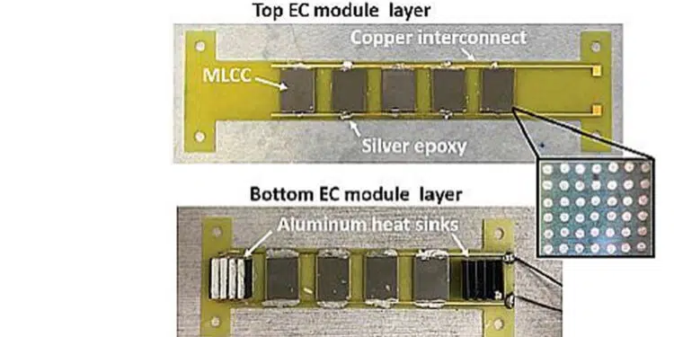
Also key to the design is the use of plates that enhance heat exchange between their layers but are good thermal insulators in the lateral direction. There is nothing exotic about their construction. They are basically glass-reinforced epoxy (FR-4) laminates and copper made via a standard commercial PCB process. In the regions of the plate where the MLCCs attach, plated-copper through-vias serve as thermal shunts for high through-plane thermal conductivity.

The MLCCs are assembled onto the plates to form the top and bottom EC modules containing five and four MLCCs, respectively. The bottom module has an aluminum plate-fin heat sink at each end to facilitate temperature stability. The modules sit in a 3D-printed VeroClear housing filled with polyurethane foam insulation. Besides providing structural support, the housing also minimizes heat leakage. A miniature fan at one end pushes air across the hot-end heat sink.
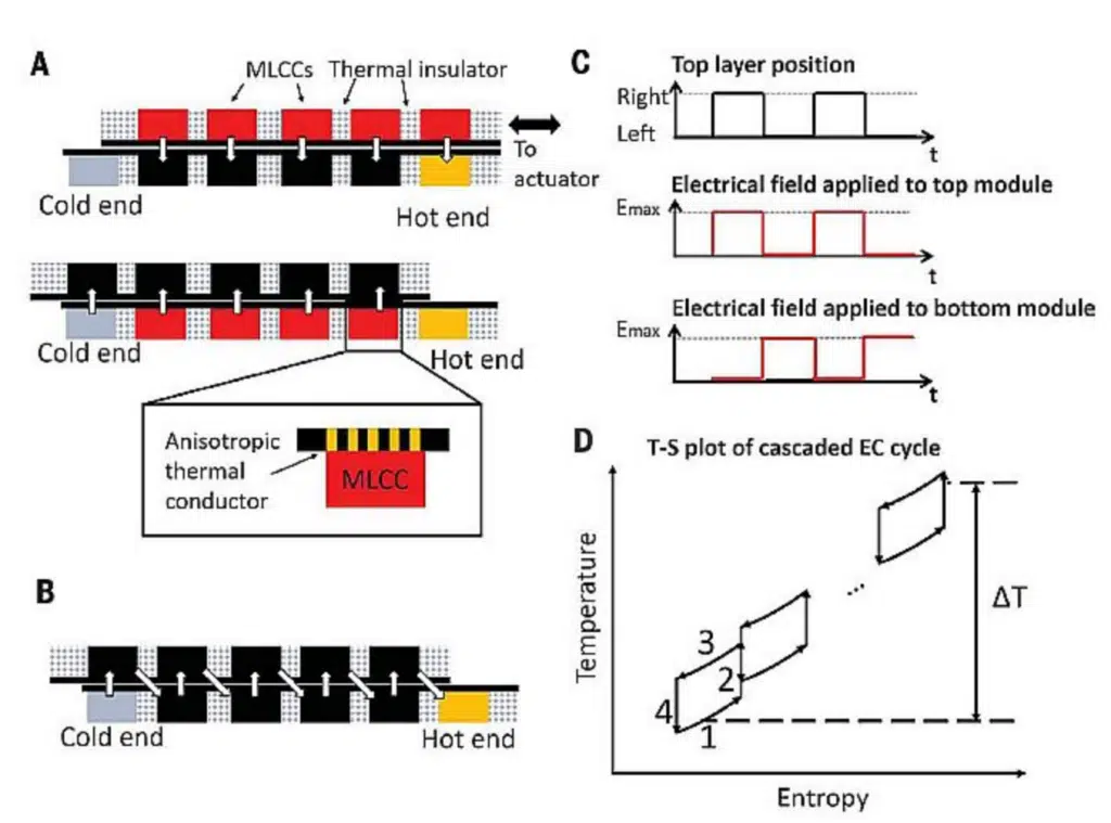
Operation of the EC system as described by the Xerox PARC/Murata research team. (A) Relative positions of the EC modules in the two heat transfer stages. (B) The heat flow path. (C) The electric field and actuation timing. (D) Schematic of the Brayton cycle as observed for each MLCC

The top housing connects to a spring-returned single-acting linear solenoid actuator with about a half-inch of stroke. In operation, energizing the actuator draws the top module toward the actuator. When the voltage returns to zero, the solenoid relaxes and a spring returns it to its original position. The EC module housing provides vertical pressure through a set of wheels to keep good thermal contact between the two modules. Control software synchronizes the movement of the top module layer with the application of electric fields to the EC capacitors.

The MLCCs operate via a Brayton cycle, with two zero-voltage and two equal-entropy stages. The scheme uses a 400-V polarizing voltage (equivalent to ~10.5-MV/m electric field) and a 0.2-Hz switching frequency (5-sec period) with about a 50% duty cycle. There are heat sinks at both ends of the device. Over the course of the experiments, heat sink temperature on the hot end rises, while the temperature at the cold end changes in discrete steps as the heater power varies.

The cooling power seen in this small demonstration device is only on the order of hundreds of milliwatts per square centimeter. A more interesting question concerns its COP. Researchers say the EC system COP is a function of the heat collected from the cold side of the device, the additional electrical work associated with charging and discharging the EC capacitor, and the amount of electrical energy recovered each cycle. There’s also mechanical and electrical work required to move the reciprocating system, but that was so small that researchers figured they could safely ignore it. Factoring in all these parameters, they calculated a COP for the experimental setup that is about equal to that of existing Peltier devices.

Given all the possible improvements, researchers estimate EC-powered A/C using existing PST capacitor material might eventually hit COPs of about 56.4%, making their system competitive with vapor compression cooling.

Related

Source: DesignWorld

Recent Posts

Enhancing Energy Density in Nanocomposite Dielectric Capacitors

9.10.2025
6

Advances in the Environmental Performance of Polymer Capacitors

8.10.2025
16

Vishay Releases DLA Tantalum Polymer Capacitors for Military and Aerospace

8.10.2025
10

Paumanok Releases Capacitor Foils Market Report 2025-2030

7.10.2025
13

Modelithics Welcomes CapV as a Sponsoring MVP

7.10.2025
3

Benefits of Tantalum Powder Stress–Strain Curve Evaluation vs Conventional Wet Test

3.10.2025
20

Electrolyte Selection and Performance in Supercapacitors

3.10.2025
17

Connector PCB Design Challenges

3.10.2025
21

Researchers Demonstrated High Energy Ceramic Capacitors Stable in Wide Temperature Range

2.10.2025
24

How to Manage Supercapacitors Leakage Current and Self Discharge 

1.10.2025
42

Upcoming Events

Oct 14
16:00 - 17:00 CEST

Smart Sensors, Smarter AI: Building Reliable Edge Systems

Oct 17
12:00 - 14:00 EDT

External Visual Inspection per MIL-STD-883 TM 2009

Oct 20
October 20 - October 23

Digital WE Days 2025 – Virtual Conference

Oct 21
October 21 @ 12:00 - October 23 @ 14:15 EDT

Space and Military Standards for Hybrids and RF Microwave Modules

Oct 28
8:00 - 15:00 CET

Power Up Your Design: SN6507 and the Ready-to-Use Development Kit

View Calendar

Popular Posts

  • Buck Converter Design and Calculation

    0 shares
    Share 0 Tweet 0
  • Boost Converter Design and Calculation

    0 shares
    Share 0 Tweet 0
  • Flyback Converter Design and Calculation

    0 shares
    Share 0 Tweet 0
  • LLC Resonant Converter Design and Calculation

    0 shares
    Share 0 Tweet 0
  • What is a Dielectric Constant and DF of Plastic Materials?

    4 shares
    Share 4 Tweet 0
  • SEPIC Converter Design and Calculation

    0 shares
    Share 0 Tweet 0
  • Dual Active Bridge (DAB) Topology Explained

    0 shares
    Share 0 Tweet 0
  • Ripple Current and its Effects on the Performance of Capacitors

    3 shares
    Share 3 Tweet 0
  • MLCC and Ceramic Capacitors

    0 shares
    Share 0 Tweet 0
  • Flying Capacitors Explained

    0 shares
    Share 0 Tweet 0

Newsletter Subscription


Passive Components Blog

© EPCI - Leading Passive Components Educational and Information Site

  • Home
  • Privacy Policy
  • EPCI Membership & Advertisement
  • About

No Result
View All Result
  • Home
  • Knowledge Blog
  • Premium Suppliers

© EPCI - Leading Passive Components Educational and Information Site

This website uses cookies. By continuing to use this website you are giving consent to cookies being used. Visit our Privacy and Cookie Policy.
Go to mobile version