Wireless power transfer offers many advantages, including the elimination of power cords and the increase of safety and durability. Reliability and safety are both critical for users and regulated by third parties. Selection and consideration of use of MLCC ceramic capacitors is discussed in this article published by Kemet blog.
From watches and phones to electric vehicles, wireless power transfer (WPT) systems for charging batteries are becoming ubiquitous. Wireless power transfer offers many advantages, including the elimination of power cords and the increase of safety and durability.
Automotive applications always require special care, and WPT in electric vehicles is no exception. Reliability and safety are both critical for users and regulated by third parties. So properly understanding, selecting, and using components is of the utmost importance.
How a Wireless Power Transfer Resonant Circuit Works
In electronic circuits, a resonant circuit is formed whenever an inductor (L) and capacitor (C) are connected. The values of the L and C form a resonant frequency, which is the frequency at which the circuit will resonate, continuing to oscillate on its own after an initial introduction of energy.
Resonance effect
Resonance occurs when an LC circuit is driven from an external source at an angular frequency ω0 at which the inductive and capacitive reactances are equal in magnitude. The frequency at which this equality holds for the particular circuit is called the resonant frequency. The resonant frequency of the LC circuit is

where L is the inductance in henries, and C is the capacitance in farads. The angular frequency ω0 has units of radians per second.
The equivalent frequency in units of hertz is

In an ideal circuit, this resonating circuit would continue to oscillate indefinitely, but in real life, there are impedances involved in every real circuit that won’t allow perpetual resonance. But resonant circuits still have a lot of value when it comes to wireless power transfer circuits.
(Source: https://en.wikipedia.org/wiki/Resonant_inductive_coupling)
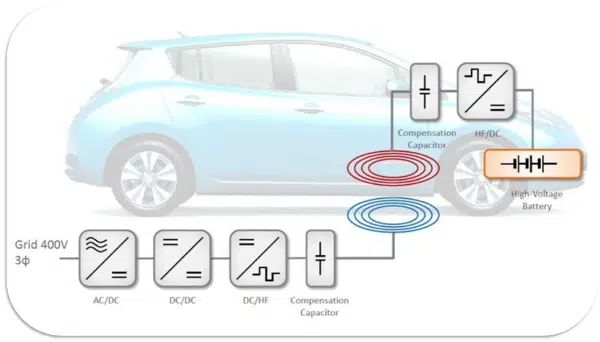
In its most basic form, a wireless power transfer resonant circuit works by powering an oscillator that is inductively coupled to a resonant circuit in the target device. That resonant circuit causes the inductive coupling to strengthen, creating a higher efficiency power transfer. That transferred power is then rectified and used by the load in the target device.
More advanced versions of WPT resonant circuits use a resonant circuit on both the source and load sides or have other improvements and advanced designs, but the basic fundamental concept of the resonant circuit for WPT remains the same.
Where MLCCs Fit In
Multilayer ceramic capacitors (MLCCs) can be used with an inductor to create a resonant circuit. MLCCs are ideal for WPT resonant circuits because of their high-frequency operation, low ESR/ESL, and are non-polarized.
For many applications, it may be difficult or impossible to find a single ceramic capacitor with high enough capacitance that meets the other circuit voltage requirements. Multiple MLCCs in parallel can be used in this case to get the capacitance needed. However, multiple MLCCs in parallel come with a cost. The physical arrangement of parallel surface mount capacitors introduces a lot of parasitic characteristics, ESR, and ESL. There are some lead-frame structures available for stacking and using MLCCs more like a single component, and those can help, though they still introduce increased ESR and ESL, in addition to being physically less robust.
MLCC manufacturers are offering “stacked” MLCC construction that allows two, three, or four ceramic capacitors to be stacked vertically or side by side. KEMET offers a patented technology called KONNEKT that allows vertical stacking without using any metal strips on the sides. This technology can withstand high heat, allowing it to be used in existing reflow processes.
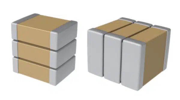
Stacking ceramic capacitors on top of each other is a way to solve the problem of tight spaces. Because of the increasing miniaturization of electronic devices and the requirements for smaller electronic components with more capabilities, higher ratings, and robust reliability, a smaller footprint on a circuit board is critical. Traditionally, components are stacked on top of each other to conserve space and to hold them in place, using metal beds – or lead frames. However, lead frames are costly and introduce power loss.
KEMET KONNEKT technology creates a low loss, low inductance package capable of handling high temperatures and high power while taking up a very small footprint on the board.
Example Application Circuit Design
Let’s look at an example design. For this design, we will be designing the capacitor selection for a WPT resonant circuit for an electric vehicle charging system.
For this system, we will need to select the appropriate capacitor for a WPT system defined as follows:
- AC Voltage: 350Vrms
- DC Voltage: 0V
- AC Current: 12.3Arms
- Frequency: 85kHz
- Application Temperature: 55°C
- Resonant Capacitance Required 66nF
Step 1: Determine the Minimum DC Voltage Rating
To determine the minimum DC voltage rating needed for the capacitor, there are two rules that both must be satisfied:
Rule #1 is that the DC rating of the capacitor must be larger than the peak AC voltage plus the DC voltage in the application.
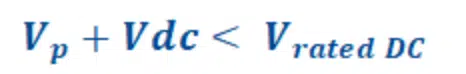
Rule #2 is that the peak voltage (Vp) must be less than half the rated DC voltage.

In our case:
The peak voltage (Vp) is half of the AC peak-to-peak voltage (Vpp). This leaves us with:
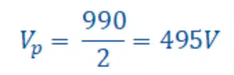
So to satisfy Rule #1, the DC rated voltage must be greater than 495V.
Given the rated voltage determined from Rule #1, we get the following:


So to satisfy Rule #2, the DC rated voltage must be greater than 990V.
Step 2: Find a Capacitor that Meets the Requirements
Now that we know the required capacitance (66nF) and DC voltage rating (> 990V) for our WPT resonant circuit application, we need to find a suitable capacitor. Lets take an example of KEMET’s KC-LINK capacitors that are ideal for resonant applications, so let’s look at their offerings. The following table is from the KC-LINK datasheet, found here.
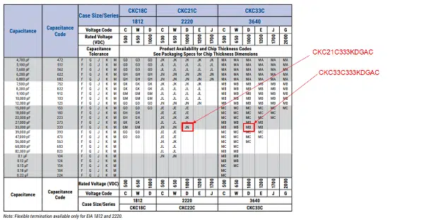
While KEMET’s KC-LINK capacitors are ideal for resonant applications, there are no 66nF capacitors available rated for > 990V. However, there are two options for 33nF capacitors rated at 1000VDC, as shown in the table, in package case sizes 2220 and 3640.
Utilizing KEMET’s KONNEKT technology, these two capacitors can be stacked and used as a single 66nF, 1000VDC capacitor.
Step 3: Determine Ripple Current Capability
Now that two possible capacitors have been identified, we must determine the ripple current capability of each to see if either will work in our application. Using KEMET’s free online circuit simulator, KSIM (https://ksim3.kemet.com/), we can simulate the ripple current in each device:
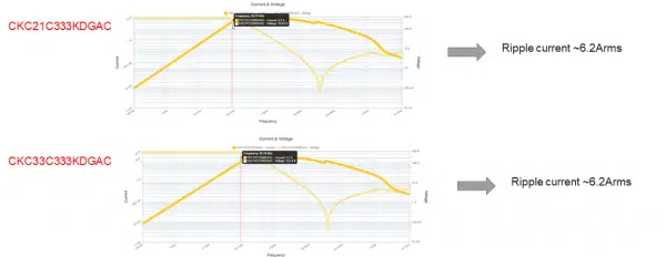
For each of the capacitors under evaluation, the ripple current is ~6.2Arms. Stacking two devices together using KEMET’s KONNEKT technology gives us a total ripple current capability of 12.4Arms, which is above our application current of 12.3Arms. Therefore, either of these capacitors could be used in this application.
Voltage and Current Limited Regions
Two other considerations when analyzing a capacitor’s voltage and current ratings in AC applications are their operation in the voltage-limited and current-limited regions.
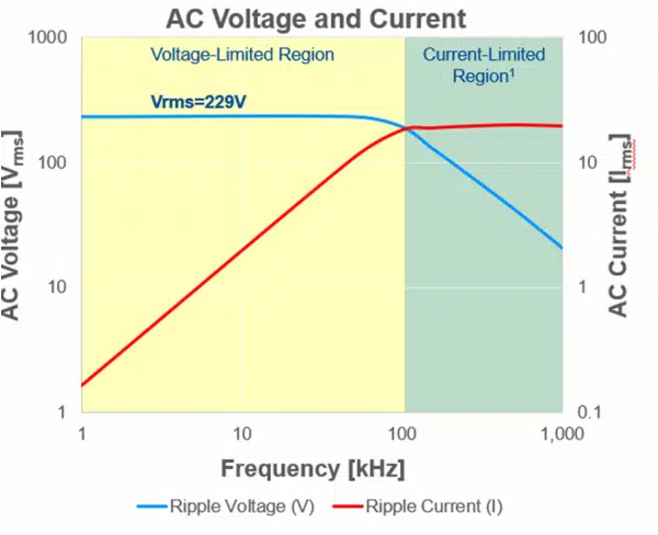
As demonstrated in the sample graph, at lower frequencies the voltage rating is the limiting factor, while at higher frequencies the current rating is the limiting factor. At a certain frequency, there is a crossover point.
In the voltage-limited region, the primary risk to MLCCs is breakdown or damage due to high AC voltages. Proper capacitor selection and derating for the operating environments and conditions are important to ensure reliable operation in this region.
In the current-limited region, the primary risk to MLCCs is breakdown or damage due to self-heating. Every real-life capacitor has an equivalent series resistance (ESR), and as frequencies and/or capacitance increases for the same AC voltage, the AC current increases through the capacitor. For this reason, it is again critical to select capacitors with low ESR and derated properly for the application.
Conclusion
For wireless power transfer (WPT) resonant circuits, stacked MLCC capacitors, offer an ideal solution. KEMET’s KC-LINK capacitors, stacked together with their patented KONNEKT technology can withstand high heat, allowing it to be used in existing reflow processes.
WPT resonant circuits used to power and charge electric vehicles are likely to become more common, and more advanced and improved solutions are on their way.