Passive Components Blog
No Result
View All Result
  • Home
  • NewsFilter
    • All
    • Aerospace & Defence
    • Antenna
    • Applications
    • Automotive
    • Capacitors
    • Circuit Protection Devices
    • electro-mechanical news
    • Filters
    • Fuses
    • Inductors
    • Industrial
    • Integrated Passives
    • inter-connect news
    • Market & Supply Chain
    • Market Insights
    • Medical
    • Modelling and Simulation
    • New Materials & Supply
    • New Technologies
    • Non-linear Passives
    • Oscillators
    • Passive Sensors News
    • Resistors
    • RF & Microwave
    • Telecommunication
    • Weekly Digest

    YAGEO Introduces 310VAC SMD Y2 Safety MP Capacitors for Compact EMI Filtering

    DMASS: European Components Distribution Returns To Growth In Q1 2026

    German Component Distribution Market Rebounds in Q1 2026 According to FBDi

    Nippon Chemi-Con Announces New Capacitor series for AI, Automotive and Immersion Cooling

    Ultrahigh Energy Storage in Lead‑Free BiFeO₃‑Based Ceramic Capacitors via Local Polar Structure Design

    Molex Expanded AirBorn SInergy Hybrid Connectors with 25 A Power Modules

    Murata Expands Ansys Simulation Models for RF inductors, MLCCs, and Power Inductors

    Sumida Introduces SMD Metal Inductors for High‑Current Automotive DC/DC Converters

    Hirose Releases 0.5 mm Floating Board-to-Board Connector for EV Powertrain Designs

    Trending Tags

    • Ripple Current
    • RF
    • Leakage Current
    • Tantalum vs Ceramic
    • Snubber
    • Low ESR
    • Feedthrough
    • Derating
    • Dielectric Constant
    • New Products
    • Market Reports
  • VideoFilter
    • All
    • Antenna videos
    • Capacitor videos
    • Circuit Protection Video
    • Filter videos
    • Fuse videos
    • Inductor videos
    • Inter-Connect Video
    • Non-linear passives videos
    • Oscillator videos
    • Passive sensors videos
    • Resistor videos

    Why Isolated DC/DC Power Supplies Fail Late, Würth Elektronik Podcast

    Designing 800 V DC EMC Filters: Calculation, Simulation and Measurement

    Current Sense Transformer Datasheet and Design‑in Guide

    Designing a USB Type‑C Flyback Planar Transformer with Frenetic’s Planar Tool

    Magnetics Design in High‑Frequency GaN Converters

    Qi2 Wireless Charging: Inductors, Capacitors and EMC Filters

    Two‑capacitor paradox explained for engineers

    Capacitances of Nonlinear MLCCs: What Datasheets Don’t Tell You

    Tapped Inductor Buck Converter Fundamentals

    Trending Tags

    • Capacitors explained
    • Inductors explained
    • Resistors explained
    • Filters explained
    • Application Video Guidelines
    • EMC
    • New Products
    • Ripple Current
    • Simulation
    • Tantalum vs Ceramic
  • Knowledge Blog
  • DossiersNew
  • Suppliers
    • Who is Who
  • PCNS
    • PCNS 2025
    • PCNS 2023
    • PCNS 2021
    • PCNS 2019
    • PCNS 2017
  • Events
No Result
View All Result
Passive Components Blog
No Result
View All Result

Modelling of Supercapacitor Charging Dynamics

24.8.2022
Reading Time: 4 mins read
A A

A new model more accurately predicts the charging time of real supercapacitors by better accounting for the structure of the device’s porous electrodes.

The development of novel electrolytes and electrodes for supercapacitors is hindered by a gap of several orders of magnitude between experimentally measured and theoretically predicted charging timescales. Cheng Lian of Utrecht University in the Netherlands and colleagues have developed a new model, containing many parallel stacked electrodes, that explains the slow charging dynamics of supercapacitors and predicts charging times much closer to real values. The result may help researchers design safer and more effective devices for energy storage.

RelatedPosts

YAGEO Introduces 310VAC SMD Y2 Safety MP Capacitors for Compact EMI Filtering

DMASS: European Components Distribution Returns To Growth In Q1 2026

German Component Distribution Market Rebounds in Q1 2026 According to FBDi

At low applied potentials, the charging behavior of this model is described well by an equivalent circuit model. Conversely, at high potentials, charging dynamics slow down and evolve on two relaxation time scales: a generalized RC time and a diffusion time, which, interestingly, become similar for porous electrodes. The charging behavior of the stack-electrode model presented here helps to understand the charging dynamics of porous electrodes and qualitatively agrees with experimental time scales measured with porous electrodes.

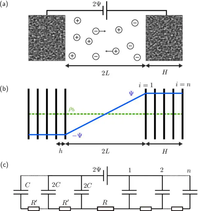
The porous electrodes used in some supercapacitors are sponge-like materials with nanometer-sized pores. This structure means that they pack a huge surface area into a tiny volume—up to a square kilometer in a cube 10 cm to a side. This property lets a supercapacitor store an enormous charge without requiring a large voltage, making it a safe and space-efficient way to store electrical energy. But the large surface area has a downside: it means they take a long time to fully charge. Previous models represented the electrodes either as single-pore structures that failed to capture an electrode’s vast surface area or as single-plate affairs that ignored their porous structures. These simplifications resulted in the models significantly underestimating charging times.

In their new model, Lian and colleagues approximate the porous structure of an electrode with a series of infinitesimally thin parallel plates that are separated by gaps that are the width of a typical pore. Their model predicts charging times that are off by only a factor of 2 or 3 from experimental measurements of real supercapacitors.

Figure 1. (a) Sketch of a supercapacitor containing a 1:1 electrolyte, two porous electrodes, and a battery providing an electrostatic potential difference 2Ψ. (b) In our stack electrode model, the cathode and anode each contain n planar electrodes at intervals of h. Initial anionic and cationic densities are ρ b throughout the cell. At time t = 0, −Ψ and +Ψ are applied to all electrodes on the left and right-hand sides of the system, respectively. (c) Equivalent circuit model for the stack-electrode model. Source: Utrecht University

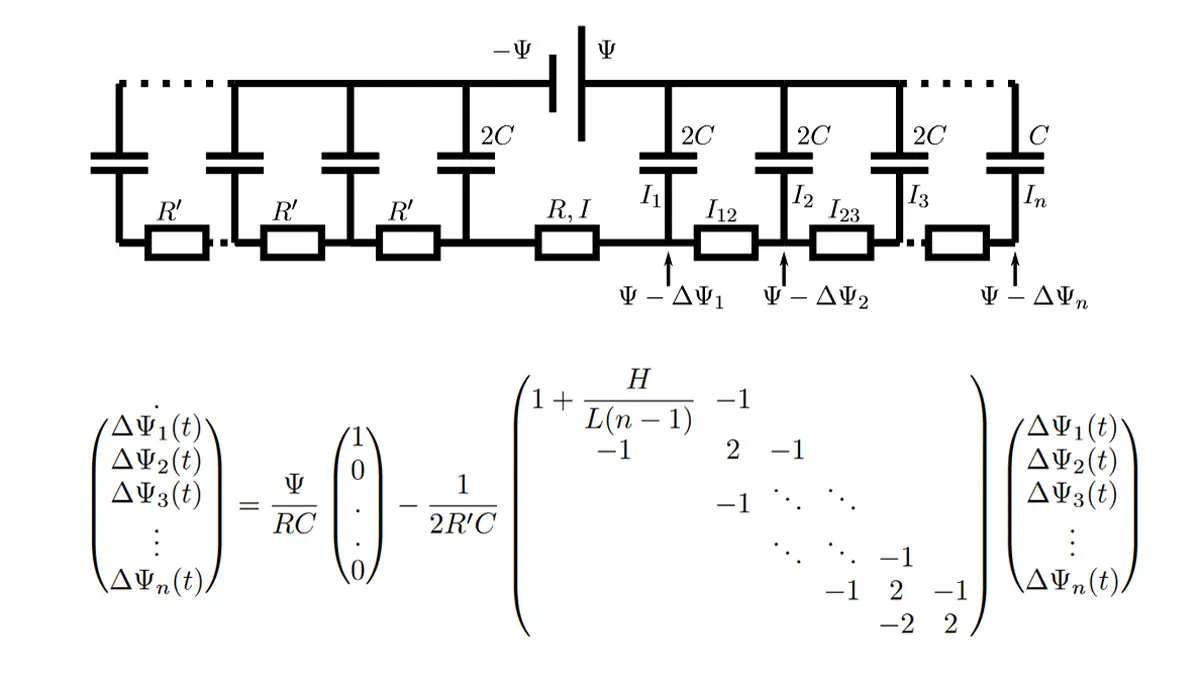
In summary, authors studied the charging dynamics of nanoporous electrodes with a simple electrode model. At small applied potentials, numerical simulations of the PNP equations are reproduced accurately by an equivalent circuit model.

This circuit model is akin to TL models used often to fit experimental supercapacitor data. Notably, however, the resistances, capacitance, and number of branches in the circuit model are not fit parameters but physically determined by the evaluated microscopic model. This one-to-one relation allows to interpret the long relaxation time of supercapacitors as being due to the large number of pores in nanoporous electrodes: The stack-electrode model relaxes with the time scale τn∼(2 + 0.75H/L)nτRC.

At higher potentials, the surface charge still relaxes at early times with τn. Higher potentials also lead to slow salt adsorption in the EDLs and concomitant depletion of the reservoir on the time scale τad∼(L+H)2/D. As salt and charge transport are coupled, the long time scale τ ad also governs the late-time surface charge relaxation, all the more so the higher the applied potential.

The two time scales τn and τad differ orders of magnitude for small n but become similar when electrodes have many pores, as is the case for supercapacitors. Inserting parameters relating to a re-ent experimental study, the simple model predicts the two observed relaxation times roughly within 1 order of magnitude.

The model thus successfully bridged the 5-orders-of-magnitude gap between theoretically predicted and experimentally measured timescales, and could serve as a basis for extensions that break the planar symmetry. However, more work is needed to fully understand the charging dynamics of porous electrodes, which should include effects due to finite ion sizes, more realistic modeling of pore morphology, Faradaic reactions, position-dependent diffusion coefficients, etc.

Read the full paper at DOI: 10.1103/PhysRevLett.124.076001

Related

Source: Researchgate

Recent Posts

YAGEO Introduces 310VAC SMD Y2 Safety MP Capacitors for Compact EMI Filtering

16.6.2026
2

DMASS: European Components Distribution Returns To Growth In Q1 2026

16.6.2026
5

German Component Distribution Market Rebounds in Q1 2026 According to FBDi

16.6.2026
5

Nippon Chemi-Con Announces New Capacitor series for AI, Automotive and Immersion Cooling

16.6.2026
9

Ultrahigh Energy Storage in Lead‑Free BiFeO₃‑Based Ceramic Capacitors via Local Polar Structure Design

16.6.2026
11

Murata Expands Ansys Simulation Models for RF inductors, MLCCs, and Power Inductors

16.6.2026
9

Knowles Releases 3825 X1/Y2 Safety MLCCs for High‑Voltage Applications

11.6.2026
35

TAIYO YUDEN Releases 220uF 1210 Automotive MLCC

11.6.2026
49

HEICO’s Exxelia Expands High-Voltage Ceramic Capacitor Portfolio with CalRamic Acquisition

10.6.2026
45

Upcoming Events

Jul 14
16:00 - 17:00 CEST

EMC Design Essentials: Mastering Varistors and Common Mode Chokes

Jul 21
16:00 - 17:00 CEST

Safety by design: X and Y Interference suppression capacitors for power line filters

View Calendar

Popular Posts

  • Buck Converter Design and Calculation

    0 shares
    Share 0 Tweet 0
  • Boost Converter Design and Calculation

    0 shares
    Share 0 Tweet 0
  • LLC Resonant Converter Design and Calculation

    0 shares
    Share 0 Tweet 0
  • MLCC and Ceramic Capacitors

    0 shares
    Share 0 Tweet 0
  • Flyback Converter Design and Calculation

    0 shares
    Share 0 Tweet 0
  • Earthing Systems and IEC Classification Explained

    0 shares
    Share 0 Tweet 0
  • SEPIC Converter Design and Calculation

    0 shares
    Share 0 Tweet 0
  • Dual Active Bridge (DAB) Topology

    0 shares
    Share 0 Tweet 0
  • What Electronics Engineer Needs to Know About Passive Low Pass Filters

    0 shares
    Share 0 Tweet 0
  • MLCC Case Sizes Standards Explained

    0 shares
    Share 0 Tweet 0

Newsletter Subscription


Passive Components Blog

© EPCI - Leading Passive Components Educational and Information Site

  • Home
  • Privacy Policy
  • EPCI Membership & Advertisement
  • About

No Result
View All Result
  • Home
  • Knowledge Blog
  • Dossiers
  • PCNS

© EPCI - Leading Passive Components Educational and Information Site

This website uses cookies. By continuing to use this website you are giving consent to cookies being used. Visit our Privacy and Cookie Policy.
Go to mobile version