Passive Components Blog
No Result
View All Result
  • Home
  • NewsFilter
    • All
    • Aerospace & Defence
    • Antenna
    • Applications
    • Automotive
    • Capacitors
    • Circuit Protection Devices
    • electro-mechanical news
    • Filters
    • Fuses
    • Inductors
    • Industrial
    • Integrated Passives
    • inter-connect news
    • Market & Supply Chain
    • Market Insights
    • Medical
    • Modelling and Simulation
    • New Materials & Supply
    • New Technologies
    • Non-linear Passives
    • Oscillators
    • Passive Sensors News
    • Resistors
    • RF & Microwave
    • Telecommunication
    • Weekly Digest

    Wk 42 Electronics Supply Chain Digest

    Stackpole Introduces Automotive Thick Film Wide Termination Chip Resistors

    September 2025 ECIA US Components Sales Sentiment Continues in Optimism

    Bourns Release Automotive 4-Terminal Shunt Resistors

    Bourns Releases High Inductance Common Mode Choke

    Vishay Releases Automotive TO-220 Case 50W Thick Film Power Resistor

    High Energy Density Polymer Film Capacitors via Molecular and Interfacial Design

    Bourns Releases High Clearance and Creepage 1500VDC Power Transformer

    KYOCERA AVX Expands Stacked MLCC Capacitors Offering

    Trending Tags

    • Ripple Current
    • RF
    • Leakage Current
    • Tantalum vs Ceramic
    • Snubber
    • Low ESR
    • Feedthrough
    • Derating
    • Dielectric Constant
    • New Products
    • Market Reports
  • VideoFilter
    • All
    • Antenna videos
    • Capacitor videos
    • Circuit Protection Video
    • Filter videos
    • Fuse videos
    • Inductor videos
    • Inter-Connect Video
    • Non-linear passives videos
    • Oscillator videos
    • Passive sensors videos
    • Resistor videos

    Connector PCB Design Challenges

    Efficient Power Converters: Duty Cycle vs Conduction Losses

    Ripple Steering in Coupled Inductors: SEPIC Case

    SEPIC Converter with Coupled and Uncoupled Inductors

    Coupled Inductors in SEPIC versus Flyback Converters

    Non-Linear MLCC Class II Capacitor Measurements Challenges

    Percolation Phenomenon and Reliability of Molded Power Inductors in DC/DC converters

    Root Causes and Effects of DC Bias and AC in Ceramic Capacitors

    How to Calculate the Output Capacitor for a Switching Power Supply

    Trending Tags

    • Capacitors explained
    • Inductors explained
    • Resistors explained
    • Filters explained
    • Application Video Guidelines
    • EMC
    • New Products
    • Ripple Current
    • Simulation
    • Tantalum vs Ceramic
  • Knowledge Blog
  • Suppliers
    • Who is Who
  • PCNS
    • PCNS 2025
    • PCNS 2023
    • PCNS 2021
    • PCNS 2019
    • PCNS 2017
  • Events
No Result
View All Result
Passive Components Blog
No Result
View All Result

MOSFETs as the best automating balancing solution for supercapacitors

1.3.2019
Reading Time: 4 mins read
A A

Source: Electronic Products news

By Robert Chao, president and founder, Advanced Linear Devices, Inc. MOSFETs lower the operating bias voltage of the supercapacitor, balancing the circuit’s power burn, and can automatically adjust to temperature, time, and environmental changes.

RelatedPosts

Wk 42 Electronics Supply Chain Digest

Stackpole Introduces Automotive Thick Film Wide Termination Chip Resistors

September 2025 ECIA US Components Sales Sentiment Continues in Optimism

Design teams are now eyeing supercapacitors for a range of new products in energy harvesting, office automation, backup systems, and more. These supercapacitor cells provide efficient storage that can quickly discharge energy on demand. To ensure peak performance and a long product life cycle, the supercapacitor’s voltage must be balanced. If an imbalance occurs due to leakage current differences between the cells, an energy drain could be triggered, causing the supercapacitor cells to fail prematurely.

Supercapacitors, also known as ultracapacitors, provide high power, rapid charging and discharging, peak-power shaving, and backup power functions for mission-critical data-protection and battery-backup applications. They are becoming a popular choice for applications in which the need for power doesn’t exceed 30 seconds.

Supercapacitors are also raising the bar on energy density. As the cells gradually increase power density, they can buffer and store energy more effectively — thus maximizing energy-gathering efforts.

Here’s the rub: Each supercapacitor has a tolerance difference in capacitance, internal resistance, and leakage current. This may create an imbalance in cell voltage. Supercapacitors must be balanced to ensure that the voltage doesn’t exceed the supercapacitor’s maximum voltage rating.

Power system designers should select supercapacitors from the same manufacturer to make sure that the initial cell voltage values fall into a similar range. Second, there must be compensation for any cell voltage imbalance caused by leakage current in individual cells.

There are two types of balancing methods used to regulate voltage in supercapacitor cells: active and passive. A low-value resistor is used in a passive balancing method. This method dissipates power and doesn’t respond to the temperature variations. Active balancing techniques are achieved with operational amplifiers (op-amps) or current balancing using MOSFETs.

Below are two scenarios with supercapacitors stacked in a series. The first scenario presents supercapacitors with auto-balancing, and the second presents supercapacitors without auto-balancing. The differences between these two design scenarios will demonstrate the need for a balancing method that automatically corrects the effects of changing leakage currents.

Supercapacitors without auto-balancing
Leakage current can cause voltage imbalance and power dissipation. Power system designers must compensate for the leakage current from each individual supercapacitor cell. Otherwise, the supercapacitor’s operating life can be reduced or even permanently damaged if the excess voltage surpasses the rated voltage of a cell for a prolonged time period.

The below illustration (Fig. 1) presents two supercapacitors connected in series without the aid of an auto-balancing mechanism. It depicts how the leakage current moves up and down with differential voltage. If not balanced, this issue can cause failure due to overvoltage effects.


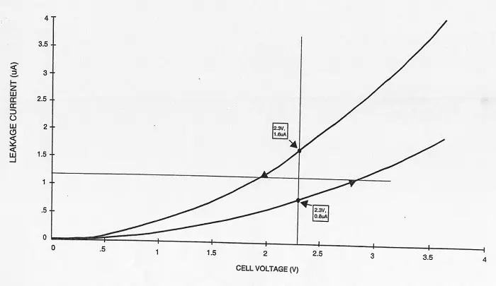
Fig. 1: A view of two supercapacitors connected in series without an auto-balancing mechanism.

Fig. 1 illustrates that at 2.3 V, the upper supercapacitor has a leakage current of 1.6 µA, while the lower supercapacitor exhibits leakage current of 0.8 µA. If these two supercapacitors don’t balance and equalize the leakage current, the lower supercapacitor can permanently fail due to the excessive voltage.

Supercapacitors with auto-balancing
Fig. 2 illustrates how MOSFETS balance supercapacitors by lowering the operating bias voltage of the supercapacitor, thus balancing the circuit’s power burn.


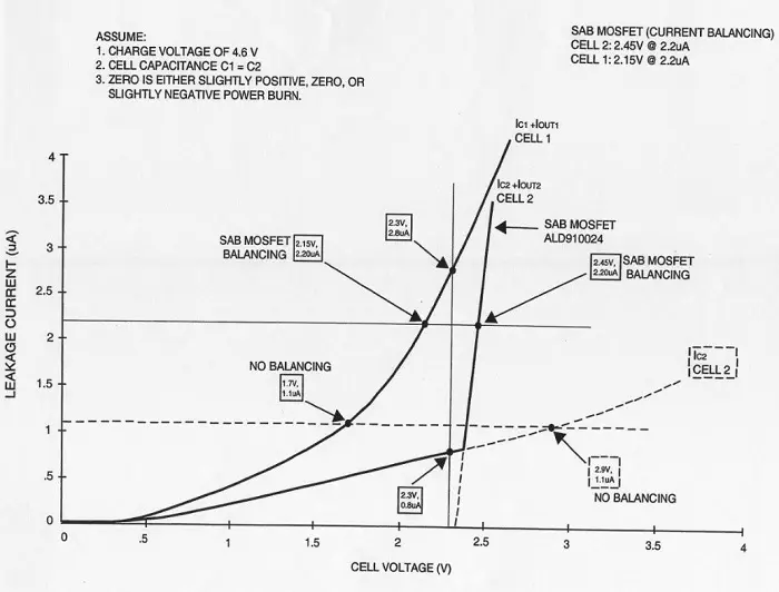
Fig. 2: Two supercapacitors connected in series accomplish superior auto-balancing using a MOSFET chip.

Supercapacitors without auto-balancing, denoted by the dotted horizontal line above, can subsequently damage cells due to overvoltage. The solid horizontal line marks the current balancing operation using a MOSFET device. When a MOSFET is connected across a supercapacitor in an array, a small rise in voltage caused by leakage current from another supercapacitor leads to a larger decline in on-resistance (RDS(ON)) of that MOSFET. This causes a hike in the supercapacitor’s current, subsequently reducing the voltage.

The principle of auto-balancing uses the natural threshold characteristics of the MOSFET device. At the threshold voltage, the MOSFET turns on and starts to conduct a current. That feature ensures that there is little or no additional leakage current from the MOSFET chip.

Fig. 2 also shows how the op-amp voltage-balancing method forces the two supercapacitor cells to reach the same voltage at the mid-point of 2.3 V. However, in doing so, the two cells consume some power. If the capacitance of the two cells is not adequately balanced, that causes additional power burn. Consequently, there is a significant waste of energy during the process of automated balancing with the op-amps. In addition, op-amps dissipate power themselves through their circuit networks.

Unlike op-amps, which can cause a power penalty if there is a mismatch between the capacitance values of two cells, MOSFETs enable natural cell balancing through complementary opposing current levels.

In addition, supercapacitor cell 1 and supercapacitor cell 2 in Fig. 2 are interchangeable. Therefore, it is unknown which one has more leakage current. Some of the current comes from the MOSFET itself, not supercapacitor cell 2.

The MOSFET-based leakage current balancing mechanism is fully automated, and it works with nearly all supercapacitors. This auto-balancing technique requires no additional current drain, and it can automatically adjust to temperature, time, and environmental changes.

From MOSFET to board

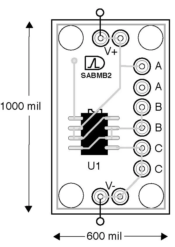
Plug-and-play printed circuit boards (PCBs) can be populated with MOSFETS that automatically balance leakage current and voltage of supercapacitor cells. A single MOSFET or multiple MOSFETs can be mounted on the supercapacitor automatic balancing (SAB) PCBs to automatically balance the supercapacitor cells.


Fig. 3 on left: A block diagram of an SABMB2 board, measuring 0.6 × 1 inch, for supercapacitor automatic balancing.

As an example, ALD’s plug-and-play SAB PCBs can be used for prototyping or production designs. These boards can be cascaded to form a series chain, ranging from two to hundreds for balancing supercapacitor stacks.

Related

Recent Posts

High Energy Density Polymer Film Capacitors via Molecular and Interfacial Design

15.10.2025
19

KYOCERA AVX Expands Stacked MLCC Capacitors Offering

14.10.2025
36

Over-Voltage Protection Clippers, Clampers, Snubbers, DC Restorers

13.10.2025
28

Silicon Capacitors Market: Shaping the Foundation for Next-Gen Miniaturization Electronics

10.10.2025
61

Enhancing Energy Density in Nanocomposite Dielectric Capacitors

9.10.2025
36

Advances in the Environmental Performance of Polymer Capacitors

8.10.2025
65

Vishay Releases DLA Tantalum Polymer Capacitors for Military and Aerospace

8.10.2025
29

Paumanok Releases Capacitor Foils Market Report 2025-2030

7.10.2025
29

Modelithics Welcomes CapV as a Sponsoring MVP

7.10.2025
5

Benefits of Tantalum Powder Stress–Strain Curve Evaluation vs Conventional Wet Test

3.10.2025
27

Upcoming Events

Oct 20
October 20 - October 23

Digital WE Days 2025 – Virtual Conference

Oct 21
October 21 @ 12:00 - October 23 @ 14:15 EDT

Space and Military Standards for Hybrids and RF Microwave Modules

Oct 28
8:00 - 15:00 CET

Power Up Your Design: SN6507 and the Ready-to-Use Development Kit

View Calendar

Popular Posts

  • Buck Converter Design and Calculation

    0 shares
    Share 0 Tweet 0
  • Boost Converter Design and Calculation

    0 shares
    Share 0 Tweet 0
  • Flyback Converter Design and Calculation

    0 shares
    Share 0 Tweet 0
  • LLC Resonant Converter Design and Calculation

    0 shares
    Share 0 Tweet 0
  • Ripple Current and its Effects on the Performance of Capacitors

    3 shares
    Share 3 Tweet 0
  • What is a Dielectric Constant and DF of Plastic Materials?

    4 shares
    Share 4 Tweet 0
  • SEPIC Converter Design and Calculation

    0 shares
    Share 0 Tweet 0
  • MLCC and Ceramic Capacitors

    0 shares
    Share 0 Tweet 0
  • Dual Active Bridge (DAB) Topology

    0 shares
    Share 0 Tweet 0
  • Flying Capacitors

    0 shares
    Share 0 Tweet 0

Newsletter Subscription


Passive Components Blog

© EPCI - Leading Passive Components Educational and Information Site

  • Home
  • Privacy Policy
  • EPCI Membership & Advertisement
  • About

No Result
View All Result
  • Home
  • Knowledge Blog
  • PCNS

© EPCI - Leading Passive Components Educational and Information Site

This website uses cookies. By continuing to use this website you are giving consent to cookies being used. Visit our Privacy and Cookie Policy.
Go to mobile version