Passive Components Blog
No Result
View All Result
  • Home
  • NewsFilter
    • All
    • Aerospace & Defence
    • Antenna
    • Applications
    • Automotive
    • Capacitors
    • Circuit Protection Devices
    • electro-mechanical news
    • Filters
    • Fuses
    • Inductors
    • Industrial
    • Integrated Passives
    • inter-connect news
    • Market & Supply Chain
    • Market Insights
    • Medical
    • Modelling and Simulation
    • New Materials & Supply
    • New Technologies
    • Non-linear Passives
    • Oscillators
    • Passive Sensors News
    • Resistors
    • RF & Microwave
    • Telecommunication
    • Weekly Digest

    Littelfuse Adds 600W Automotive TVS Diodes for High-Energy Transient Protection

    Vishay Releases Harsh Environment Robust DC-Link Film Capacitor

    Bourns Releases Automotive High Creepage and Clearance Transformer

    Bourns Unveils Metal Powder Core High Current Low DCR Shielded Power Inductor

    Influence of Tantalum Capacitor Pellets Size on Stability During Oxide Film Formation

    Modelithics Release Discrete Components Optimization Article for RF/Microwave Designers

    Samsung Extends Capacitance of MLCC 0805 X7T 250V to 100nF

    Samtec Releases 800-Position High-Performance Array Connectors  

    DigiKey Announces Back to School Giveaway to Empower Tomorrow’s Innovators

    Trending Tags

    • Ripple Current
    • RF
    • Leakage Current
    • Tantalum vs Ceramic
    • Snubber
    • Low ESR
    • Feedthrough
    • Derating
    • Dielectric Constant
    • New Products
    • Market Reports
  • VideoFilter
    • All
    • Antenna videos
    • Capacitor videos
    • Circuit Protection Video
    • Filter videos
    • Fuse videos
    • Inductor videos
    • Inter-Connect Video
    • Non-linear passives videos
    • Oscillator videos
    • Passive sensors videos
    • Resistor videos

    Ripple Steering in Coupled Inductors: SEPIC Case

    SEPIC Converter with Coupled and Uncoupled Inductors

    Coupled Inductors in SEPIC versus Flyback Converters

    Non-Linear MLCC Class II Capacitor Measurements Challenges

    Percolation Phenomenon and Reliability of Molded Power Inductors in DC/DC converters

    Root Causes and Effects of DC Bias and AC in Ceramic Capacitors

    How to Calculate the Output Capacitor for a Switching Power Supply

    Switched Capacitor Converter Explained

    Understanding Inductor Dot Markings and Their Application in LTspice

    Trending Tags

    • Capacitors explained
    • Inductors explained
    • Resistors explained
    • Filters explained
    • Application Video Guidelines
    • EMC
    • New Products
    • Ripple Current
    • Simulation
    • Tantalum vs Ceramic
  • Knowledge Blog
  • Suppliers
    • Who is Who
  • Events
No Result
View All Result
Passive Components Blog
No Result
View All Result

Non-Noble Finish Degradation Mechanisms

7.9.2021
Reading Time: 6 mins read
A A

Because tin is the most commonly used non-noble contact finish, it will be the focus of this chapter. Silver and nickel finishes are also used with silver being a good choice for power connectors and nickel commonly used as a battery contact material.

Fretting Corrosion of Tin Contact Interfaces

RelatedPosts

Polymer Materials and Processing

What is RF Connector

Connector Materials and Processes

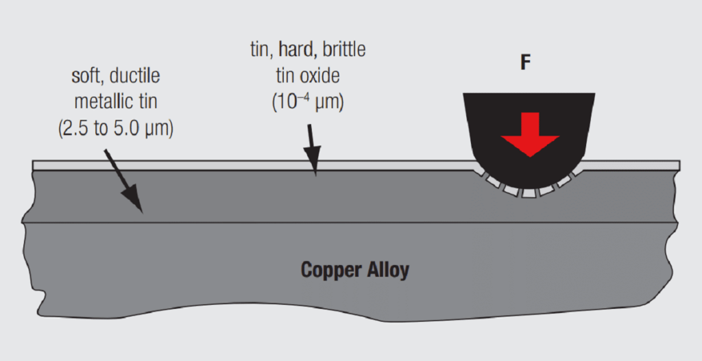
As noted previously the dominant degradation mechanism for tin contact finishes is fretting corrosion. Before discussing the mechanism of fretting corrosion a review of the kinetics of creating a tin-to-tin contact interface as schematically illustrated in Figure 2.10 is in order. The contact probe applies a load to the tin oxide covered tin surface. Because the tin oxide is very thin, hard and brittle, it cracks under the applied load. The load then transfers to the tin, which is soft and ductile, causing the tin to flow and the cracks in the oxide to spread apart. The tin then extrudes into the cracks in the oxide creating a tin-to-tin contact interface with the tin plating on the contact probe which has experienced a similar deformation and displacement of its tin finish. This mechanism is even more effective when the probe slides against the mating surface as it would in the mating of a connector. The sliding action effectively pushes aside the tin oxide layers creating the desired tin-to-tin interfaces. Creating the initial contact interface is easily accomplished.

Fig. 2.10: Disrupted tin oxide surface on tin

The problem is that any exposed tin that does not make contact to a tin surface will reoxidize to create a new tin oxide layer over the tin. This is the mechanism of fretting corrosion as schematically illustrated in Figure 2.11. Figure 2.11a shows the original tin oxide disruption and displacement as just described. If, however, the contact interface moves under some applied shear stress in the application environment two things happen as indicated in Figure 2.11b. First, the sliding action during the motion disrupts and displaces the tin oxide at the new contact area creating a new tin-to-tin contact interface. At the same time the exposed tin at the initial contact area reoxidizes. After this single movement there will be little, if any, change in contact resistance. If, however, multiple movements occur, such movements are referred to as fretting; additional oxide debris will accumulate in the area of the contact as indicated in Figure 2.11c. This debris will not be as easily displaced as the original oxide layer because it is particulate rather than continuous and may be pressed down into the tin rather than being displaced. Eventually the entire sliding track consists of accumulated oxide debris, Figure 2.11d, and the contact may approach open circuit resistance values.

Fig. 2.11: Mechanism of fretting corrosion

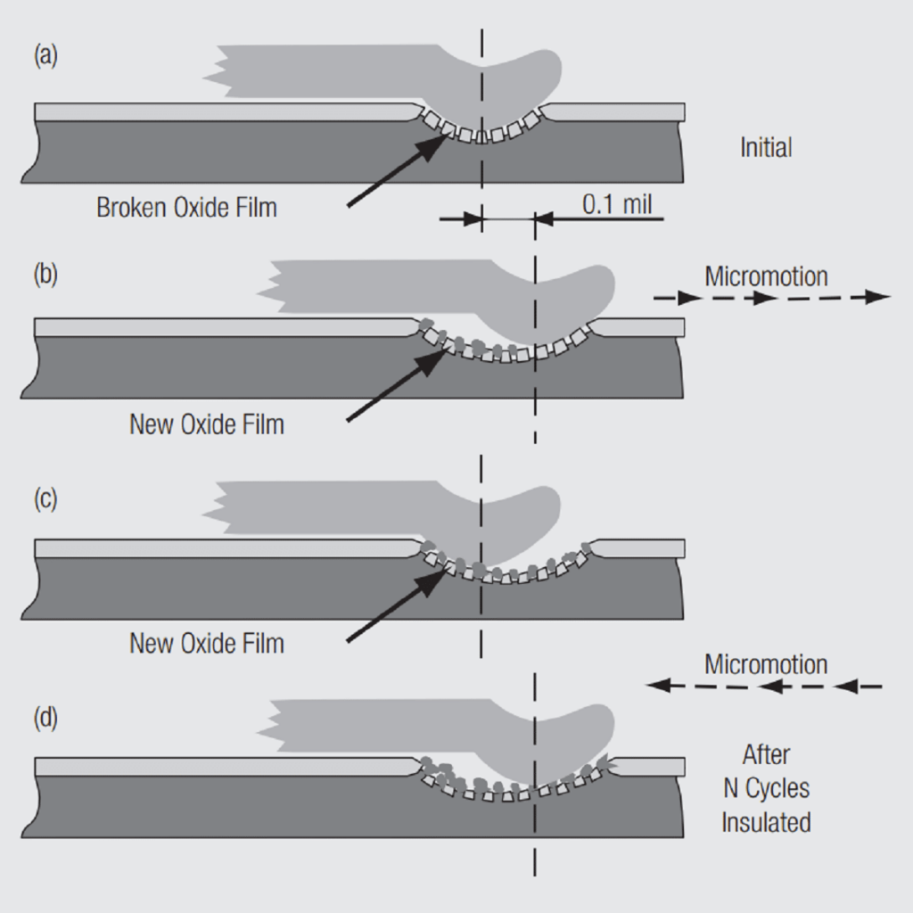
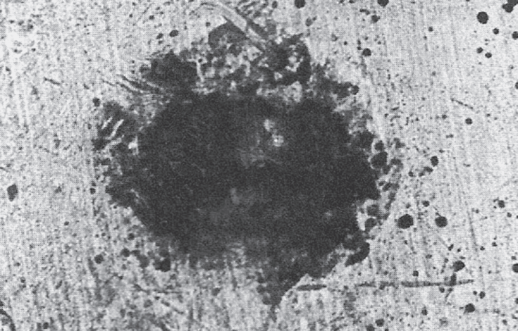
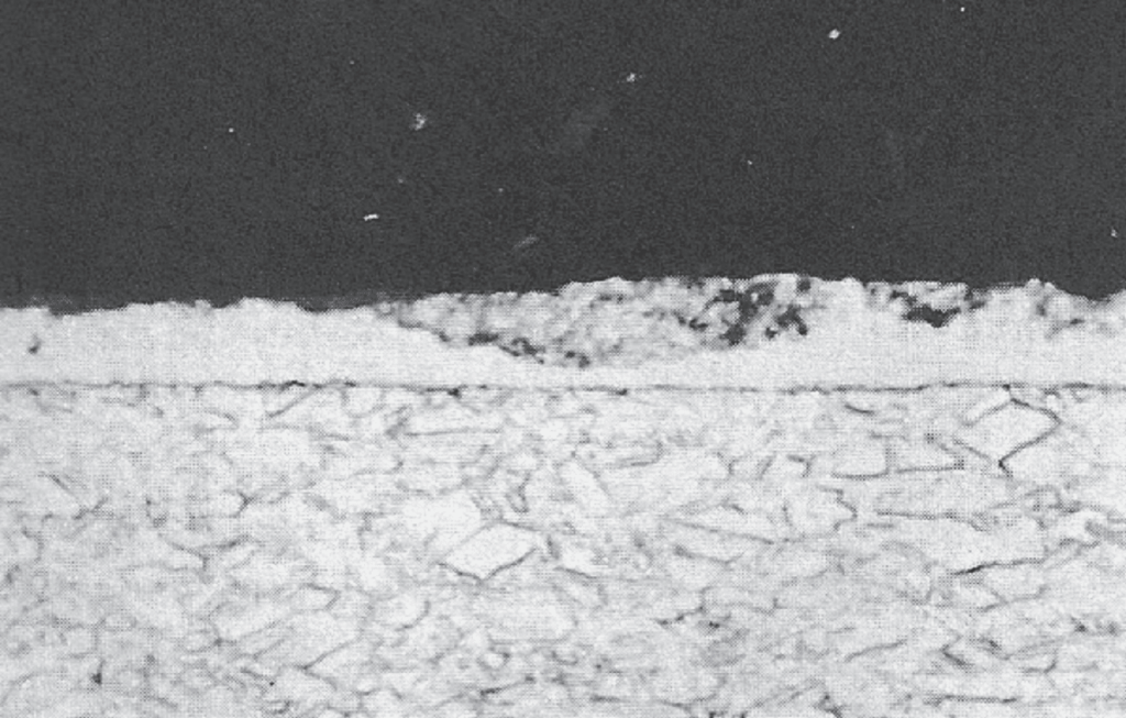
Figure 2.12 shows a contact area after fretting corrosion. The oxide particulates are very small resulting in a black appearance of the fretted interface. Such black spots are typically the first diagnostic indication of fretting corrosion during failure analysis. A cross section of a fretted spot is shown in Figure 2.13. Note the mix of tin and oxide debris that makes displacement of the debris problematic after a number of fretting cycles.

Fig. 2.12: Fretting corrosion spot
Fig. 2.13: Fretting corrosion spot cross section

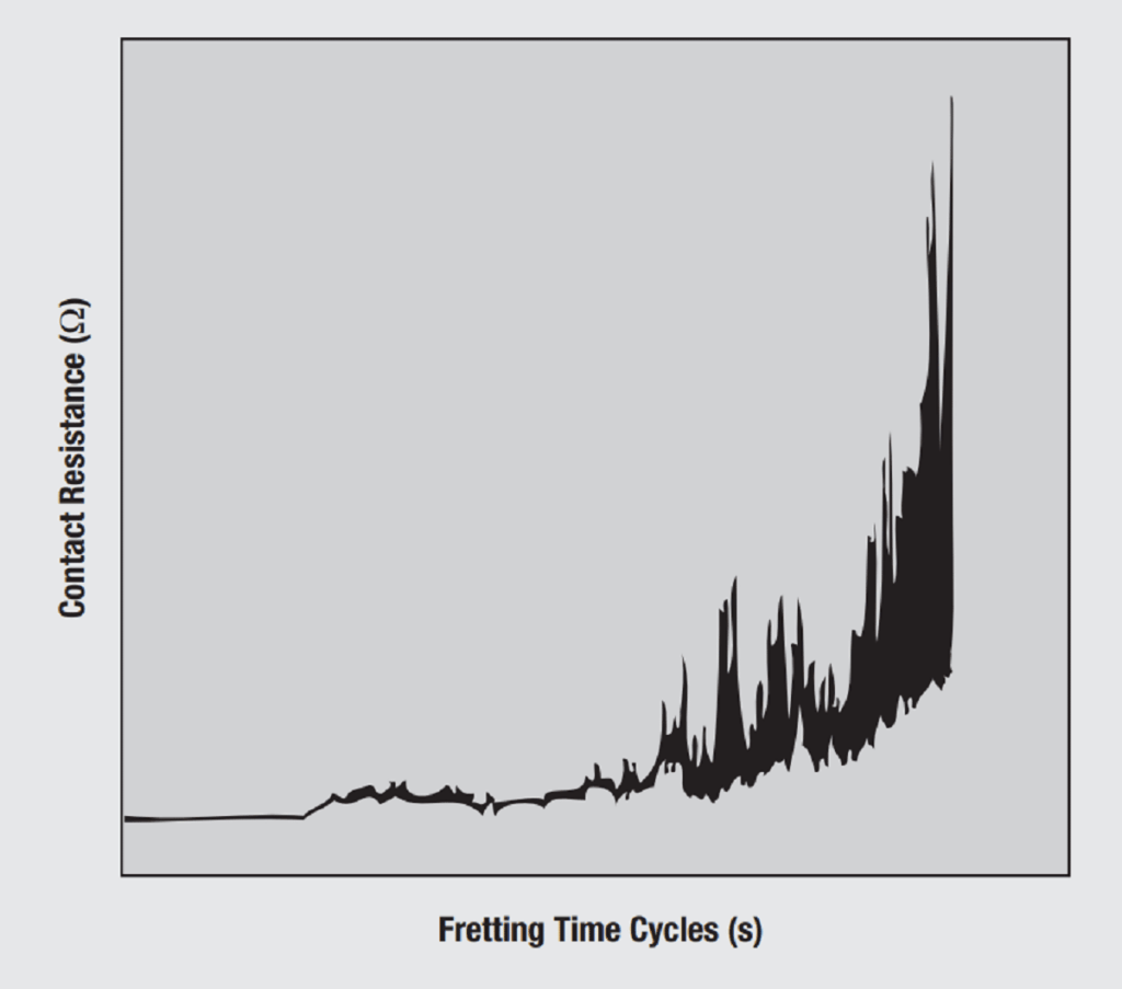
This accumulation of tin oxide debris, the corrosion part of fretting corrosion, will, over time, result in an increase in the contact resistance. The change in resistance may appear first as intermittent increases in resistance. Over time the average resistance will increase and the intermittent resistance swings will increase in magnitude and duration as schematically illustrated in Figure 2.14. The intermittent resistances may appear as electrical noise, but the increase in duration and magnitude may eventually disrupt system operation. Fretting resistance increases can increase to the tens or hundreds of ohms or even result in open circuits. Significant increases in resistance, tens of ohms, can occur after a few thousand fretting cycles.

Fig. 2.14: Intermittent resistance during fretting corrosion

The rate of fretting corrosion degradation depends on several factors. The two most important are the contact force and the length of the fretting motion. The contact force dependence arises from the fact that increased contact force results in increased wear particle formation as previously discussed. The length dependence is due to the typical build up of wear debris at the ends of the sliding track. A longer fretting track may take longer to accumulate the wear debris necessary to cause resistance increases all along the track. The length of the fretting track depends on the driving force for the fretting motion. It is important to note, however, that fretting motions of a few to several tens of µm can lead to significant fretting corrosion degradation.

The driving forces for fretting motions are both mechanical and thermal and are obviously application dependent. Mechanical drivers include both shock and vibration. Thermal driving forces arise from thermal expansion coefficient mismatches between connector housings and PCBs or other system components due to thermal cycling. Rapid thermal cycles are referred to as thermal shock. Slower cycles, for example temperature differences due to on-off cycling of equipment, are more frequent causes of fretting motions.

There are two approaches towards prevention of fretting corrosion degradation. One is to eliminate the fretting motions and the other to eliminate the corrosion, the reoxidation of the tin during fretting motions.

One means of eliminating fretting motions is the use of high contact forces to create high friction forces at the contact interfaces. This is why tin plated contacts typically have contact forces of 100 grams and higher. There are, of course, limits to how much contact force can be used in a connector as will be discussed in Chapter II/2.2 Contact Springs. At this point it is sufficient to note that tin plated contacts place additional limits on contact force because tin is a soft material with high wear rates (low mating durability) and high friction (high mating force) as a function of contact force. It is important to note, however, that if the increase in contact force is not sufficient to ensure mechanical stability the rate of fretting degradation increases with contact force, as noted previously, and the connector may be more susceptible to fretting corrosion.

The second approach, eliminating oxidation, can be realized by using a contact lubricant specifically formulated for this purpose. Contact lubricants will be discussed later but a few comments on anti-fretting lubricants are appropriate at this point.

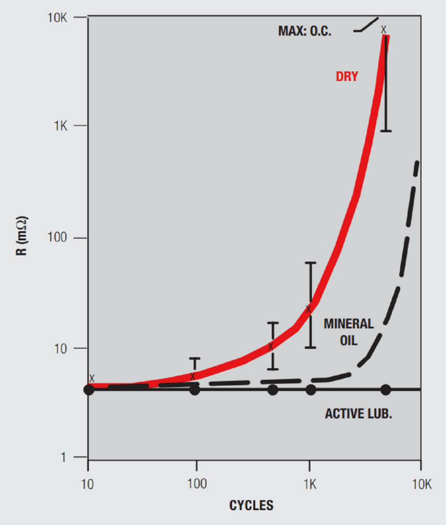
Consider the data in a Figure 2.15 which schematically illustrates contact resistance as a function of the number of fretting cycles for three different cases of surface treatment. The first case, dry, indicates a contact interface that has received no intentional lubricant. In the second case mineral oil has been applied to the contact interface. In the third case a specially formulated, anti-fretting, contact lubricant has been applied.

With no lubricant, dry, the contact resistance begins to increase at a few hundred fretting cycles with an increasing rate occurring at about 1000 cycles. Adding mineral oil to the contact interface results in a much longer stable resistance regime. But after a few thousand cycles fretting degradation begins to occur and quite rapidly. The reason for the increased degradation is loss of the mineral oil at the contact interface with time. Mineral oil has a low viscosity and flows away from the contact interface as well as evaporating. The anti-fretting lubricant (Figure 2.15) shows stable resistance out to tens of thousands of fretting cycles, demonstrating that appropriate contact lubricants can maintain contact resistance stability under fretting driving conditions.

Fig. 2.15: Effect of contact lubricant on fretting corrosion

Related

Source: Wurth elektronik

Recent Posts

Non-Magnetic Interconnects

23.4.2025
26

10 Tips for Ensuring Reliability of Discrete Wire Assemblies

20.2.2025
55

Polymer Materials and Processing

11.8.2025
50

Basic PCB Technology Overview

1.7.2025
21

What is RF Connector

17.12.2024
12

Creepage and Clearance of Connector

25.7.2025
19

Microwave Multi Line Connectors Mounting and Handling Precautions

11.8.2025
3

BASIC PCB Design Rules – Layout

1.7.2025
32

MEMR RF Relay for Space Compact Redundancy Ring

17.12.2024
3

Connector Temperature Rise and Derating

13.1.2023
26

Upcoming Events

Sep 3
15:30 - 17:30 CEST

How to Choose Your Magnetic Supplier

Sep 16
17:00 - 18:00 CEST

EMI Shielding Challenges

Sep 22
September 22 @ 13:00 - September 25 @ 15:15 EDT

Pre Cap Visual Inspection per Mil-Std-883 (TM 2017)

Sep 30
September 30 @ 12:00 - October 2 @ 14:00 EDT

MIL-Std-883 TM 2010

Oct 17
12:00 - 14:00 EDT

External Visual Inspection per MIL-STD-883 TM 2009

View Calendar

Popular Posts

  • Buck Converter Design and Calculation

    0 shares
    Share 0 Tweet 0
  • Boost Converter Design and Calculation

    0 shares
    Share 0 Tweet 0
  • Flyback Converter Design and Calculation

    0 shares
    Share 0 Tweet 0
  • LLC Resonant Converter Design and Calculation

    0 shares
    Share 0 Tweet 0
  • What is a Dielectric Constant and DF of Plastic Materials?

    4 shares
    Share 4 Tweet 0
  • Ripple Current and its Effects on the Performance of Capacitors

    3 shares
    Share 3 Tweet 0
  • Dual Active Bridge (DAB) Topology Explained

    0 shares
    Share 0 Tweet 0
  • How to Design an Inductor

    0 shares
    Share 0 Tweet 0
  • Core Materials, Permeability and Their Losses

    0 shares
    Share 0 Tweet 0
  • MLCC Case Sizes Standards Explained

    0 shares
    Share 0 Tweet 0

Newsletter Subscription


Passive Components Blog

© EPCI - Leading Passive Components Educational and Information Site

  • Home
  • Privacy Policy
  • EPCI Membership & Advertisement
  • About

No Result
View All Result
  • Home
  • Knowledge Blog
  • Premium Suppliers

© EPCI - Leading Passive Components Educational and Information Site

This website uses cookies. By continuing to use this website you are giving consent to cookies being used. Visit our Privacy and Cookie Policy.
Go to mobile version