Passive Components Blog
No Result
View All Result
  • Home
  • NewsFilter
    • All
    • Aerospace & Defence
    • Antenna
    • Applications
    • Automotive
    • Capacitors
    • Circuit Protection Devices
    • electro-mechanical news
    • Filters
    • Fuses
    • Inductors
    • Industrial
    • Integrated Passives
    • inter-connect news
    • Market & Supply Chain
    • Market Insights
    • Medical
    • Modelling and Simulation
    • New Materials & Supply
    • New Technologies
    • Non-linear Passives
    • Oscillators
    • Passive Sensors News
    • Resistors
    • RF & Microwave
    • Telecommunication
    • Weekly Digest

    3-Phase EMI Filter Design, Simulation, Calculation and Test

    YAGEO Unveils Compact 2.4 GHz SMD Antenna

    KYOCERA AVX Releases Antenna for Iridium Satellite IoT Applications

    Molex Releases Industry-First Quad-Row Board-to-Board Connectors with EMI Shields

    Image credit: Samtec

    How to Match the Right Connector with Protocol Requirements

    Smoltek CNF-MIM Capacitors Pass 1,000h Reliability Test

    Capacitor Lead Times: October 2025

    Paumanok Unveils Aluminum Capacitor Foils World Markets Study 2025-2030

    Coilcraft Introduces Ultra-Low Loss Shielded Power Inductors

    Trending Tags

    • Ripple Current
    • RF
    • Leakage Current
    • Tantalum vs Ceramic
    • Snubber
    • Low ESR
    • Feedthrough
    • Derating
    • Dielectric Constant
    • New Products
    • Market Reports
  • VideoFilter
    • All
    • Antenna videos
    • Capacitor videos
    • Circuit Protection Video
    • Filter videos
    • Fuse videos
    • Inductor videos
    • Inter-Connect Video
    • Non-linear passives videos
    • Oscillator videos
    • Passive sensors videos
    • Resistor videos

    3-Phase EMI Filter Design, Simulation, Calculation and Test

    Transformer Design Optimization for Power Electronics Applications

    Common Mode Chokes Selection for RF Circuits in Next-Generation Communication Systems

    Capacitor Self-balancing in a Flying-Capacitor Buck Converter

    How to Select Ferrite Bead for Filtering in Buck Boost Converter

    Power Inductors Future: Minimal Losses and Compact Designs

    Percolation Phenomenon: Degradation of Molded Power Inductors in DC/DC Converters

    Connector PCB Design Challenges

    Efficient Power Converters: Duty Cycle vs Conduction Losses

    Trending Tags

    • Capacitors explained
    • Inductors explained
    • Resistors explained
    • Filters explained
    • Application Video Guidelines
    • EMC
    • New Products
    • Ripple Current
    • Simulation
    • Tantalum vs Ceramic
  • Knowledge Blog
  • Suppliers
    • Who is Who
  • PCNS
    • PCNS 2025
    • PCNS 2023
    • PCNS 2021
    • PCNS 2019
    • PCNS 2017
  • Events
No Result
View All Result
Passive Components Blog
No Result
View All Result

Creepage and Clearance of Connector

25.7.2025
Reading Time: 2 mins read
A A

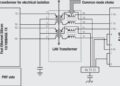
This video from Würth Elektronik elaborates on clearance and creepage distance and solid insulation materials.

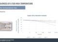
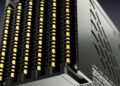
Many applications of fire are productive and warming. Fire can be a real risk if the components on pcb has not been selected correctly for high voltages.

RelatedPosts

3-Phase EMI Filter Design, Simulation, Calculation and Test

Würth Elektronik Expands its MagI³C-VDMM MicroModules

Transformer Design Optimization for Power Electronics Applications

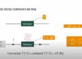
In some circumstances, incorrectly selected components can create Transient voltage, which could cause damage to the board and even leads to spark fire. To achieve electric shock protection, electronic equipment must have an effective insulation method, which can be divided in to clearance and creepage distance and solid insulation materials.

Creepage and Clearance

Creepage and clearance are crucial product safety terms and requirements for various products, assemblies, and components. Regulatory agencies like IEC, UL, and CSA establish specific product application guidelines and requirements that must be met to sell products in many countries.

Creepage and clearance standards ensure safe operation, reducing the risk of electric shocks or other injuries to end users and minimizing fire hazards. Additionally, these standards protect other components in close proximity to those being rated or tested to prevent a failure from spreading throughout the system. This discussion will focus on power interconnects, printed wiring boards (PWB/PCB), and cable assemblies.

What is Creepage?

Creepage refers to the linear distance along all insulating surfaces between two electrical conductors (as seen in Figure below). In terms of electrical measurements, this parameter essentially equates to a surface insulation resistance measurement (SIR or IR). It’s important to note that since creepage encompasses the entire surface distance between the conductors, it significantly exceeds the clearance distance of the same contacts.

What is Clearance?

Clearance refers to the distance between two electrical conductors in the air. In simpler terms, it represents the distance a spark needs to travel to cause a dielectric breakdown, as illustrated in Figure below.

Related

Source: Würth Elektronik

Recent Posts

Connector PCB Design Challenges

3.10.2025
50

Non-Magnetic Interconnects

23.4.2025
27

10 Tips for Ensuring Reliability of Discrete Wire Assemblies

20.2.2025
57

What is RF Connector

17.12.2024
15

Connector Temperature Rise and Derating

13.1.2023
37

Connector Temperature and Current Ratings Challenges

13.1.2023
20

Connector Inrush Current Explained

17.12.2024
15

Current Rating

20.9.2021
25

Power Applications

20.9.2021
8

Signal Applications

20.9.2021
1

Upcoming Events

Nov 11
17:00 - 18:00 CET

Industrial Applications Demand More from Interconnects in Next-Gen Designs

Nov 12
11:00 - 12:00 CET

PCB Design: Impedance is for everyone!

Nov 12
November 12 @ 12:00 - November 13 @ 14:15 EST

Microelectronic Packaging Failure Modes and Analysis

View Calendar

Popular Posts

  • Buck Converter Design and Calculation

    0 shares
    Share 0 Tweet 0
  • Boost Converter Design and Calculation

    0 shares
    Share 0 Tweet 0
  • LLC Resonant Converter Design and Calculation

    0 shares
    Share 0 Tweet 0
  • Flyback Converter Design and Calculation

    0 shares
    Share 0 Tweet 0
  • Ripple Current and its Effects on the Performance of Capacitors

    3 shares
    Share 3 Tweet 0
  • MLCC and Ceramic Capacitors

    0 shares
    Share 0 Tweet 0
  • Dual Active Bridge (DAB) Topology

    0 shares
    Share 0 Tweet 0
  • What is a Dielectric Constant and DF of Plastic Materials?

    4 shares
    Share 4 Tweet 0
  • SEPIC Converter Design and Calculation

    0 shares
    Share 0 Tweet 0
  • Flying Capacitors

    0 shares
    Share 0 Tweet 0

Newsletter Subscription


Passive Components Blog

© EPCI - Leading Passive Components Educational and Information Site

  • Home
  • Privacy Policy
  • EPCI Membership & Advertisement
  • About

No Result
View All Result
  • Home
  • Knowledge Blog
  • PCNS

© EPCI - Leading Passive Components Educational and Information Site

This website uses cookies. By continuing to use this website you are giving consent to cookies being used. Visit our Privacy and Cookie Policy.
Go to mobile version