Passive Components Blog
No Result
View All Result
  • Home
  • NewsFilter
    • All
    • Aerospace & Defence
    • Antenna
    • Applications
    • Automotive
    • Capacitors
    • Circuit Protection Devices
    • electro-mechanical news
    • Filters
    • Fuses
    • Inductors
    • Industrial
    • Integrated Passives
    • inter-connect news
    • Market & Supply Chain
    • Market Insights
    • Medical
    • Modelling and Simulation
    • New Materials & Supply
    • New Technologies
    • Non-linear Passives
    • Oscillators
    • Passive Sensors News
    • Resistors
    • RF & Microwave
    • Telecommunication
    • Weekly Digest

    HIROSE Releases New Field-Assembly Communication Connectors

    Coilcraft Unveils 165C High-Temperature Coupled Inductors

    Bourns Releases SMD NTC Thermistors for Thermal Sensing

    Wk 22 Electronics Supply Chain Digest

    Samsung Electro-Mechanics High Capacitance MLCCs for ADAS SoCs

    Murata Expands its Automotive Common Mode Choke Coils to 150C and High Current Capability

    Bourns Releases New Current Transformer

    Skeleton Releases GrapheneGPU to Reduce AI Energy Consumption by 44% and Boosts Power by 40%

    VINATech Expands Aluminum Capacitor Portfolio with Acquisition of Enesol

    Trending Tags

    • Ripple Current
    • RF
    • Leakage Current
    • Tantalum vs Ceramic
    • Snubber
    • Low ESR
    • Feedthrough
    • Derating
    • Dielectric Constant
    • New Products
    • Market Reports
  • VideoFilter
    • All
    • Antenna videos
    • Capacitor videos
    • Circuit Protection Video
    • Filter videos
    • Fuse videos
    • Inductor videos
    • Inter-Connect Video
    • Non-linear passives videos
    • Oscillator videos
    • Passive sensors videos
    • Resistor videos

    Coupled Inductors Circuit Model and Examples of its Applications

    Inductor Resonances and its Impact to EMI

    Highly Reliable Flex Rigid PCBs, Würth Elektronik Webinar

    Causes of Oscillations in Flyback Converters

    How to design a 60W Flyback Transformer

    Modeling and Simulation of Leakage Inductance

    Power Inductor Considerations for AI High Power Computing – Vishay Video

    Coupled Inductors in Multiphase Boost Converters

    VPG Demonstrates Precision Resistor in Cryogenic Conditions

    Trending Tags

    • Capacitors explained
    • Inductors explained
    • Resistors explained
    • Filters explained
    • Application Video Guidelines
    • EMC
    • New Products
    • Ripple Current
    • Simulation
    • Tantalum vs Ceramic
  • Knowledge Blog
  • Suppliers
    • Who is Who
  • Events
No Result
View All Result
Passive Components Blog
No Result
View All Result

Performance of AEC-Q200 rated power resistors for automotive use

13.2.2019
Reading Time: 5 mins read
A A

Source: EDN article

by Bertram Schott & Adrian Michael.

RelatedPosts

HIROSE Releases New Field-Assembly Communication Connectors

Coilcraft Unveils 165C High-Temperature Coupled Inductors

Bourns Releases SMD NTC Thermistors for Thermal Sensing

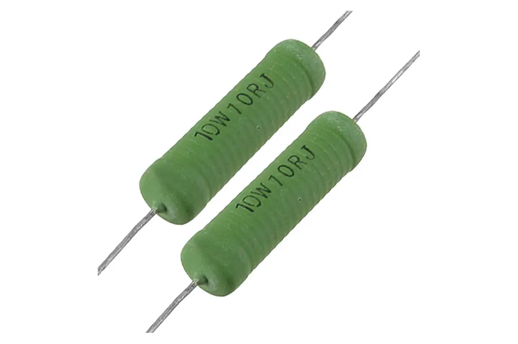
Wirewound power resistors are usually rated with respect to continuous power, which can be insufficient for e-mobility applications. A typical application is the pre- and discharge of large capacitors, often referred to as “soft start.” In this case the pulse-handling capability of the resistor is also very important. This capability can be determined over a large range of pulse durations by combining theoretical basics with finite element simulations of the respective thermal performance. The results can be generalized so that changing customer specifications can quickly be evaluated and suitable resistors suggested.

Wire allows for pulse load

Wirewound power resistors are typically specified according to their continuous power rating. However, the resistive element, the wire, can pick up a relatively large amount of energy while undergoing only a moderate temperature rise due to its relatively high mass and heat capacity. This is why wirewound power resistors are the perfect choice for pulse load applications.

Specification of the pulse load capability is important

The specification of the pulse load capability is becoming increasingly important due to the widespread use of frequency and voltage converters. The pulse load capability is often only exemplarily documented by the specification of one pulse of a certain power or energy and duration. It is rarely specified by listing a table of a few pulse amplitudes and durations. Should the resistor be stressed by a pulse for a duration that is not in the range of those given in the datasheet, and which is not in the range of adiabatic boundary conditions, then it is difficult to calculate the maximum permissible pulse load. However, a combination of theoretical basics and finite element simulations allows for calculating the thermal performance of a resistor over a virtually unlimited pulse duration interval, i.e. from very short pulses to continuous power.

e-mobility needs pulse load capability

Limiting the charge and discharge current of capacitors is a typical application for wirewound power resistors in the e-mobility sector because of the respective high pulse load. Soldering all electrical components to a PCB may be preferred instead of using “external” resistors, in order to keep the production process as simple as possible. In this case a number of smaller wirewound power resistors are directly soldered to the PCB, replacing a single large wirewound power resistor. For that type of application and manufacturing, Vishay has put the focus on the AC-AT series [1], which is the first of its kind to be AEC-Q200 automotive qualified.

Pulse load generates heat

We look at the cooling of a resistor in order to be able to evaluate the effect of an electric pulse load. An effective way to do that is to presume that Newtonian cooling prevails, i.e. that the rate of temperature change is proportional to the temperature difference of the hot resistor and its cooler ambient materials, and that the temperature of the latter is constant. In the case of a cemented wirewound resistor (e.g. of the AC-AT series), that ambient material is the cement surrounding the wire. However, the following reasoning can be applied to enameled or sand-filled wirewound resistors, too.

Pulse load at adiabatic boundary conditions

Presuming Newtonian cooling, and hence the proportionality of temporal temperature change and maximal temperature of the wire or resistor, results in an exponential function describing the time-dependent temperature of the wire and resistor [2].

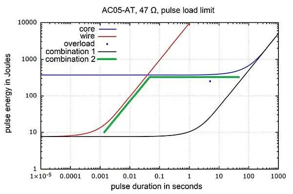
Figure 1 Pulse load limits for the ceramic core of an AC05-AT (blue curve) and the resistive wire for R = 47 Ω (red curve). Both curves are often combined: Combination 1 (black curve) underestimates the permissible overload (blue dot); Combination 2 (green line) overestimates the pulse load limit around the shown kink (at about 0.05 s).

The respective pulse load limits of the ceramic core of an AC05-AT 47 Ω resistor and its wire are shown in Figure 1 in blue and red, respectively. The maximal pulse load capability of the entire resistor is typically a simple combination of both curves. One way is an exponential function of the Newtonian cooling type, combination 1 in Figure 1, which is however far below the specified overload rating of 10 times the nominal power for 5 seconds and is therefore underestimating the pulse load capability in this range of pulse durations. Another way, combination 2 in Figure 1, overestimates the pulse load capability around the shown kink (at about 0.05 s), because the heating of the ceramic core is not taken into account when calculating temperature limits for the wire.

Finite-element (FE) simulation of pulse load

Delayed heating of the entire AC05-AT resistor under pulsating electrical load can easily be visualized by the heat flow and temperature distribution within the resistor by means of FE simulations. The resistive wire heats up during the pulse and then cools down. All other parts of the resistor are heated by that heat pulse with some delay. The duration of the pulse load does not matter in an FE simulation, as long as the boundary conditions are appropriately set. Therefore, the temperatures of the resistor and wire can be simulated for virtually any pulse duration, from adiabatic from the viewpoint of the wire (ms range) to almost continuous load of the resistor (100 s range). Consequently, the maximal permissible electrical pulse load can be determined by specifying a maximal permissible temperature of the wire.

Generalization by scaling

The results of a number of FE simulations can be generalized with respect to pulse duration by scaling with the characteristic time of thermal diffusion of the wire. This allows for the determination of a correction factor, which can be put into the exponential function, giving the temperature according to Newtonian cooling.

Pulse load at non-adiabatic boundary conditions


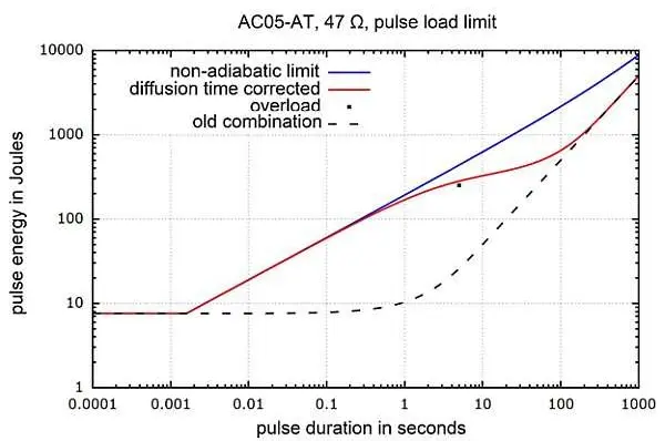
Figure 2 Maximal permissible pulse load for non-adiabatic boundary conditions from the viewpoint of the wire (blue curve) and corrected for the appropriate characteristic time of thermal diffusion (red curve). The usual limit curve with significant underestimation of the pulse load capability for pulse durations ranging from about 0.1 s to 10 s is shown for reference (black dashed line).

The above-mentioned correction factor allows for calculating the pulse load limit for non-adiabatic boundary conditions from the viewpoint of the wire (Figure 2, non-adiabatic limit). It does not yet converge to the pulse load limit of the entire resistor for long pulse durations though. However, if the characteristic time of thermal diffusion of the entire resistor is used for scaling at relatively long pulse durations, then the non-adiabatic limit curve converges to the limit curve for continuous load (Figure 2).

Application to other resistance values and resistors

The results of the FE simulations of the thermal behavior of a specific resistor (here the AC05-AT with 47 Ω) can be generalized by proper scaling. This allows them to be applied not only to all resistance values (wire configurations) available for the AC05-AT, but to all other AC-AT types, because they are of similar construction.

This method can even be applied to all other similar types of resistors, e.g. the G200 series [3], without additional FE simulations, and it is therefore extremely efficient. The advantage for the customer is that questions about pulse load capability can be answered in a timely and competent fashion.

References

  1. Cemented leaded wirewound resistors, AC, AC-AT, Vishay
  2. Bertram Schott, Estimating the pulse performance of wirewound power resistors, VDE Proceedings of PCIM Europe 2017, Nuremberg, Germany, May 2017.
  3. Axial Vitreous Leaded Wirewound Resistors, G200

Related

Recent Posts

Coilcraft Unveils 165C High-Temperature Coupled Inductors

3.6.2025
1

Samsung Electro-Mechanics High Capacitance MLCCs for ADAS SoCs

30.5.2025
26

Murata Expands its Automotive Common Mode Choke Coils to 150C and High Current Capability

29.5.2025
24

Samsung Electro-Mechanics Releases 165C Automotive 0806 Size Power Inductors

21.5.2025
36

Coupled Inductors Circuit Model and Examples of its Applications

21.5.2025
88

Würth Elektronik Introduces LTspice Models for ESD Products

21.5.2025
50

Littelfuse Gate Driver Integrates Diode and Current Limit Resistor in Compact IC

21.5.2025
22

Capacitor Ripple Current Testing: A Design Consideration

21.5.2025
75

Coilcraft Extends Air Core RF Inductors

20.5.2025
19

Bourns Releases Automotive 1W Flyback Transformer

19.5.2025
30

Upcoming Events

Jun 4
11:00 - 12:00 CEST

Würth Elektronik PCB Production in Asia

Jun 24
17:00 - 18:00 CEST

Ultra-Compact and Efficient Switched-Capacitor Power Converters

View Calendar

Popular Posts

  • Buck Converter Design and Calculation

    0 shares
    Share 0 Tweet 0
  • Boost Converter Design and Calculation

    0 shares
    Share 0 Tweet 0
  • Flyback Converter Design and Calculation

    0 shares
    Share 0 Tweet 0
  • What Electronics Engineer Needs to Know About Passive Low Pass Filters

    0 shares
    Share 0 Tweet 0
  • What is a Dielectric Constant and DF of Plastic Materials?

    4 shares
    Share 4 Tweet 0
  • LLC Resonant Converter Design and Calculation

    0 shares
    Share 0 Tweet 0
  • Coefficient of Linear Thermal Expansion on Polymers Explained

    0 shares
    Share 0 Tweet 0
  • What is the Difference Between X8G, X8L and X8R Ceramic Capacitor Dielectrics?

    0 shares
    Share 0 Tweet 0
  • Knowles Introduces High-Frequency RF Crossover

    0 shares
    Share 0 Tweet 0
  • Dual Active Bridge (DAB) Topology Explained

    0 shares
    Share 0 Tweet 0

Newsletter Subscription


Passive Components Blog

© EPCI - Leading Passive Components Educational and Information Site

  • Home
  • Privacy Policy
  • EPCI Membership & Advertisement
  • About

No Result
View All Result
  • Home
  • Knowledge Blog
  • Premium Suppliers

© EPCI - Leading Passive Components Educational and Information Site

This website uses cookies. By continuing to use this website you are giving consent to cookies being used. Visit our Privacy and Cookie Policy.
Go to mobile version