Passive Components Blog
No Result
View All Result
  • Home
  • NewsFilter
    • All
    • Aerospace & Defence
    • Antenna
    • Applications
    • Automotive
    • Capacitors
    • Circuit Protection Devices
    • electro-mechanical news
    • Filters
    • Fuses
    • Inductors
    • Industrial
    • Integrated Passives
    • inter-connect news
    • Market & Supply Chain
    • Market Insights
    • Medical
    • Modelling and Simulation
    • New Materials & Supply
    • New Technologies
    • Non-linear Passives
    • Oscillators
    • Passive Sensors News
    • Resistors
    • RF & Microwave
    • Telecommunication
    • Weekly Digest

    Supercapacitors Benefits in Industrial Valve Fail-Safe Control Systems

    Wk 21 Electronics Supply Chain Digest

    Samsung Electro-Mechanics Releases High-Capacitance MLCCs for AI Server Applications

    Samsung Electro-Mechanics Releases 165C Automotive 0806 Size Power Inductors

    Coupled Inductors Circuit Model and Examples of its Applications

    Würth Elektronik Introduces LTspice Models for ESD Products

    Capacitor Ripple Current Testing: A Design Consideration

    TDK Releases 0201 High-Frequency Smallest Inductors

    Coilcraft Extends Air Core RF Inductors

    Trending Tags

    • Ripple Current
    • RF
    • Leakage Current
    • Tantalum vs Ceramic
    • Snubber
    • Low ESR
    • Feedthrough
    • Derating
    • Dielectric Constant
    • New Products
    • Market Reports
  • VideoFilter
    • All
    • Antenna videos
    • Capacitor videos
    • Circuit Protection Video
    • Filter videos
    • Fuse videos
    • Inductor videos
    • Inter-Connect Video
    • Non-linear passives videos
    • Oscillator videos
    • Passive sensors videos
    • Resistor videos

    Coupled Inductors Circuit Model and Examples of its Applications

    Inductor Resonances and its Impact to EMI

    Highly Reliable Flex Rigid PCBs, Würth Elektronik Webinar

    Causes of Oscillations in Flyback Converters

    How to design a 60W Flyback Transformer

    Modeling and Simulation of Leakage Inductance

    Power Inductor Considerations for AI High Power Computing – Vishay Video

    Coupled Inductors in Multiphase Boost Converters

    VPG Demonstrates Precision Resistor in Cryogenic Conditions

    Trending Tags

    • Capacitors explained
    • Inductors explained
    • Resistors explained
    • Filters explained
    • Application Video Guidelines
    • EMC
    • New Products
    • Ripple Current
    • Simulation
    • Tantalum vs Ceramic
  • Knowledge Blog
  • Suppliers
    • Who is Who
  • Events
No Result
View All Result
Passive Components Blog
No Result
View All Result

Primary Fuse Protection Against Overvoltage Events

23.1.2025
Reading Time: 4 mins read
A A

Overvoltages occur during events such as switching operations, electrostatic discharges as well as lightning discharges. Be they direct or indirect, they are introduced by galvanic, inductive or capacitive means to electrical lines, with the potential to create devastating effects.

Pulse-shaped load currents are a common circuit occurrence and a typical factor for consideration when designing in primary fuses. Pulses can arise individually (Surge), or recurrently (e.g. timed circuits). With individual pulses, the I²t value of the fuse wire becomes quite important. This is because the higher the i²t value the greater the pulse tolerance; with pulse-shaped continuous currents, the calculation of the rms value is crucial, and generally the displacement of the rated current should be taken into account as a result of a possible increase in aging (diffusion).

RelatedPosts

Overvoltage Protection Selection Guidelines: TVS Diodes, MOVs, and ESD MOV Varistors

ESD Electrostatic Discharge Protection by TVS Diode

Chip Varistors Applications for ESD Countermeasures

Basic protection options

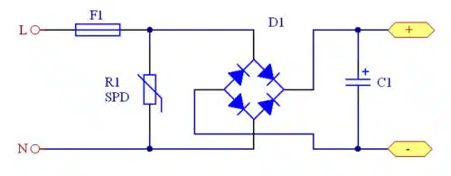
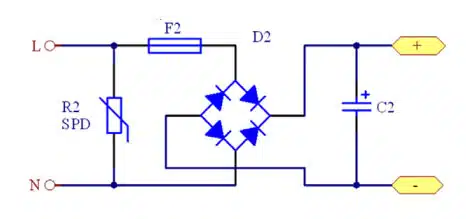
Two common circuit protection options are typically used to protect a circuit from overvoltages, a fuse for line protection together with an SPD (Surge Protection Device):

Circuit protection option P1: Fuse at the input of the circuit before the SPD
Circuit protection option P2: Fuse at the input of the circuit behind the SPD.

Comparison of protection options:

P1 represents a clean, good solution for the circuit from a technical standpoint. In particular, when using an appliance inlet with integrated fuse, this provides an elegant solution. However, greater attention has to be given to the selection of the fuse with regard to pulse tolerance, due to the fact that the SPD R1 installed downstream results in a high current load for the fuse. The result is a larger I²t value and a lower loss resistance, which increase the pulse tolerance.

The P2 wiring is more universal. Only small loads arise in the fuse, F2, due to minimal surge pulses caused by the SPD (e.g. varistor) R2 installed upstream. In this case, the designer has much more leeway when selecting the fuse.

Damages to the SPDs R1 and R2 do not necessarily trigger the fuse in either circuit variant.

Recommendation: A combination of SPD with a temperature-controlled fuse is recommended for both circuit variants P1 and P2.

Aging caused by surge pulses

When selecting fuse performance characteristics and size, it should always be kept in mind that the behavior of every fuse is changed as a result of current impulses.

The fuse wire often has a coating, which diffuses increasingly deeper into the base material. This ongoing occurrence produces a new alloy, which in turn leads to in a displacement of the rated current and a continuous weakening of the fuse.

Measurement according to IEC 61000-4-5

The ability of a device to cope with these high-energy pulses is measured according to IEC 61000-4-5 with the pulse form 8/20μs for the short-circuit current and 1.2/50μs for the open-circuit voltage. Further details for testing the pulse tolerance [2].

Setup S1 without SPD / Setup S2 with SPD Setup S1 is a surge of 8/20μs directly to fuse F1. This test achieves the highest load for the fuse through the overvoltage test. Variant S2 is a realistic setup for some applications with an SPD in a row. The combination wave overvoltage generator creates a mixed signal of 1.2/50μs voltage and 8/20μs current pulse. The fuse current values shown in the SCHURTER datasheets are tested with the S1 setup and in Unify Tests with S1 and S2. If the fuses perform properly in the circuit, they must be checked individually. There are no stated tests for fuses behind the SPD – analog to protective circuit P2 – since the overvoltage does not represent a high load for the fuse.

Note: In some of the selected SCHURTER datasheets, the fuses were tested either in the P1 arrangement, without varistor (Setup S1) or the P1 arrangement with varistor (Setup S2).

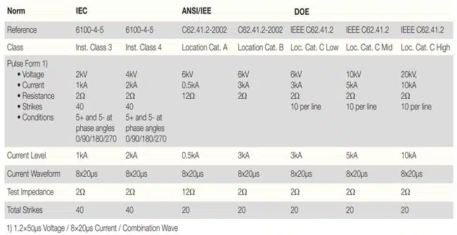
According to the tests carried out, the above pulse tolerances can be proposed in accordance with the classification into the various standard classes. The characteristic values for the respective products are listed depending on the rated current.

Test comparison according to current standards

Test comparisons between standards have been carried out, according to the differing international standards (IEC), e.g. in the USA according to ANSI and/or DOE. This is to ensure that the products tested fulfill all the local requirements.

Related

Source: Schurter

Recent Posts

Supercapacitors Benefits in Industrial Valve Fail-Safe Control Systems

26.5.2025
5

Capacitor Ripple Current Testing: A Design Consideration

21.5.2025
52

Coilcraft Extends Air Core RF Inductors

20.5.2025
16

Bourns Releases Automotive 1W Flyback Transformer

19.5.2025
20

Highly Reliable Flex Rigid PCBs, Würth Elektronik Webinar

15.5.2025
28

Würth Elektronik Releases High Performance TLVR Coupled Inductors

15.5.2025
39

YAGEO Extends Rectangular Aluminum Electrolytic Capacitor Family

15.5.2025
57

Littelfuse Releases Industry-First SMD Fuse with 1500A Interrupting Rating at 277V

14.5.2025
13

TDK Unveils Industry Highest Rated Current Multilayer Chip Beads

14.5.2025
19

Vishay Releases Automotive SMD Thick Film Power Resistor for Enhanced Protection Against Short Transient Pulses

14.5.2025
13

Upcoming Events

May 28
16:00 - 17:00 CEST

Power Over Data Line

View Calendar

Popular Posts

  • Buck Converter Design and Calculation

    0 shares
    Share 0 Tweet 0
  • Boost Converter Design and Calculation

    0 shares
    Share 0 Tweet 0
  • Flyback Converter Design and Calculation

    0 shares
    Share 0 Tweet 0
  • LLC Resonant Converter Design and Calculation

    0 shares
    Share 0 Tweet 0
  • SEPIC Converter Design and Calculation

    0 shares
    Share 0 Tweet 0
  • Ripple Current and its Effects on the Performance of Capacitors

    3 shares
    Share 3 Tweet 0
  • Wk 21 Electronics Supply Chain Digest

    0 shares
    Share 0 Tweet 0
  • Coupled Inductors Circuit Model and Examples of its Applications

    0 shares
    Share 0 Tweet 0
  • Capacitor Ripple Current Testing: A Design Consideration

    0 shares
    Share 0 Tweet 0
  • Exxelia Offers Industry Unique High Voltage MLCC Pulse Capacitors with Integrated Bleed Resistor

    0 shares
    Share 0 Tweet 0

Newsletter Subscription


Passive Components Blog

© EPCI - Leading Passive Components Educational and Information Site

  • Home
  • Privacy Policy
  • EPCI Membership & Advertisement
  • About

No Result
View All Result
  • Home
  • Knowledge Blog
  • Premium Suppliers

© EPCI - Leading Passive Components Educational and Information Site

This website uses cookies. By continuing to use this website you are giving consent to cookies being used. Visit our Privacy and Cookie Policy.
Go to mobile version