Passive Components Blog
No Result
View All Result
  • Home
  • NewsFilter
    • All
    • Aerospace & Defence
    • Antenna
    • Applications
    • Automotive
    • Capacitors
    • Circuit Protection Devices
    • electro-mechanical news
    • Filters
    • Fuses
    • Inductors
    • Industrial
    • Integrated Passives
    • inter-connect news
    • Market & Supply Chain
    • Market Insights
    • Medical
    • Modelling and Simulation
    • New Materials & Supply
    • New Technologies
    • Non-linear Passives
    • Oscillators
    • Passive Sensors News
    • Resistors
    • RF & Microwave
    • Telecommunication
    • Weekly Digest

    RF Inductors: Selection and Design Challenges for High-Frequency Circuits

    Wk 45 Electronics Supply Chain Digest

    Transformer Safety IEC 61558 Standard

    ESR of Capacitors, Measurements and Applications

    Murata Christophe Pottier Appointed President of EPCIA

    3-Phase EMI Filter Design, Simulation, Calculation and Test

    YAGEO Unveils Compact 2.4 GHz SMD Antenna

    KYOCERA AVX Releases Antenna for Iridium Satellite IoT Applications

    Molex Releases Industry-First Quad-Row Board-to-Board Connectors with EMI Shields

    Trending Tags

    • Ripple Current
    • RF
    • Leakage Current
    • Tantalum vs Ceramic
    • Snubber
    • Low ESR
    • Feedthrough
    • Derating
    • Dielectric Constant
    • New Products
    • Market Reports
  • VideoFilter
    • All
    • Antenna videos
    • Capacitor videos
    • Circuit Protection Video
    • Filter videos
    • Fuse videos
    • Inductor videos
    • Inter-Connect Video
    • Non-linear passives videos
    • Oscillator videos
    • Passive sensors videos
    • Resistor videos

    RF Inductors: Selection and Design Challenges for High-Frequency Circuits

    Transformer Safety IEC 61558 Standard

    3-Phase EMI Filter Design, Simulation, Calculation and Test

    Transformer Design Optimization for Power Electronics Applications

    Common Mode Chokes Selection for RF Circuits in Next-Generation Communication Systems

    Capacitor Self-balancing in a Flying-Capacitor Buck Converter

    How to Select Ferrite Bead for Filtering in Buck Boost Converter

    Power Inductors Future: Minimal Losses and Compact Designs

    Percolation Phenomenon: Degradation of Molded Power Inductors in DC/DC Converters

    Trending Tags

    • Capacitors explained
    • Inductors explained
    • Resistors explained
    • Filters explained
    • Application Video Guidelines
    • EMC
    • New Products
    • Ripple Current
    • Simulation
    • Tantalum vs Ceramic
  • Knowledge Blog
  • Suppliers
    • Who is Who
  • PCNS
    • PCNS 2025
    • PCNS 2023
    • PCNS 2021
    • PCNS 2019
    • PCNS 2017
  • Events
No Result
View All Result
Passive Components Blog
No Result
View All Result

Pros and Cons of MLCC Downsizing; AVX Tech Paper

20.1.2021
Reading Time: 4 mins read
A A

Advantages and disadvantages of MLCC downsizing is discussed in AVX technical papers written by Frank Hodgkinson and Maureen Strawhorne.

Abstract:

As integrated circuits (ICs) continue to pack more functionality into smaller packages, the need for bulk off-chip capacitance remains. In resonant circuits, such as phase-lock-loops (PLLs) and switching regulators, precision class one ceramic capacitor may be required.

RelatedPosts

The Tantalum Supply Chain: 2021 Global Market Update

KEMET Design it Day: Capacitors and Inductors Selection Guide for Decoupling And Filtering

Tantalum Capacitors Explained; Kemet Webinar

Such capacitors must maintain a tight capacitance range over process, voltage, and temperature variation (PVT) for the host IC to meet its performance specifications. In contrast, class two ceramic capacitors are required for nearly every IC in the form of decoupling and bypass capacitance. They may also be found in amplifier circuits, simple filters, and linear regulators where their function is less dependent on tightly specified impedance requirements.

Such requirements for class two capacitors often create a trap for the unwitting designer, who might naturally focus on voltage rating, size, and cost when choosing these devices. This is especially true when the top-level application is overly constrained by form factor. One can imagine the selection filtering process: start with an approximate capacitor value (i.e., 100 nF), choose a voltage rating with some reasonable headroom (i.e., 6.3 V), and finally, find the smallest surface mount (SMT) package (i.e., 0402) and cost combination to create room for other components and PCB routing.

Considering voltage rating and capacitance separately from package size may seem reasonable, but therein lies the potential trap. As capacitor sizes have grown smaller and smaller, manufacturers have developed new technologies to increase capacitance density to achieve standard value-package combinations. In doing so, dependencies have also been introduced that may create unexpected surprises during testing.

Tradeoffs in Capacitance Density

High permittivity is mainly a function of dielectric choice. Typical ceramic materials, titanium dioxide, for example, exhibit relative permittivity values in the tens. Ferroelectric materials, on the other hand, can achieve relative permittivities in the thousands. Most modern MLCCs are constructed using Barium Titanate (BaTiO3), which can yield relative permittivity values up to 7,000. In fact, much of the capacitor manufacturing expertise lies in the milling, casting, and sintering of this insulator.

Materials research and optimization will undoubtedly continue to provide enhanced dielectric properties in the future. Still, the primary knobs for maximizing capacitance density are the number of layers and the layer spacing. In the mid-1990s, minimum layer thicknesses were in the 5-micron range, and common capacitor values were built from several hundred layers. Nearly two decades later, the thickness of the minimum layer was reduced by a factor of ten, and capacitors with more than one thousand layers were not unusual. This miniaturization trend comes with significant tradeoffs that must be considered when selecting MLCCs during the design cycle.

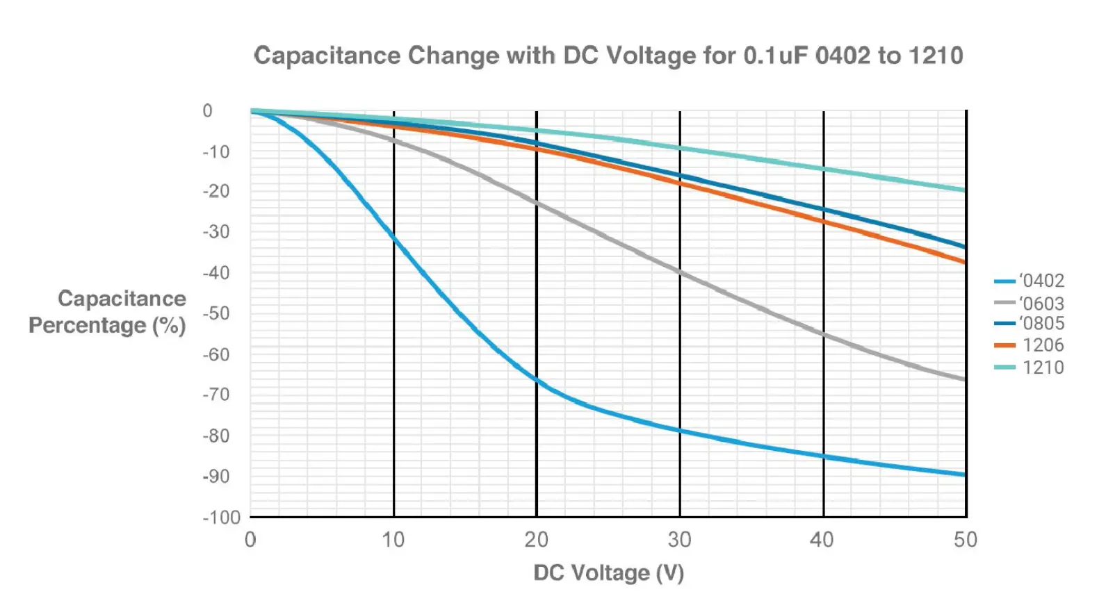
As layer thicknesses are reduced, the electric field strength through the dielectric is increased for the same applied voltage. Since the dielectric materials are typically ferroelectric, their permittivity reduces as electric field strength increases. Therefore, the same capacitor in a 0402 package will have poorer voltage dependence characteristics compared to a 0805 package. At high voltages, this can be particularly problematic. An example is shown below, where a 0402 capacitor has lost 90% of its capacitance capability at an applied voltage of 50V.

Capacitance Change with DC Voltage for 0.1uF 0402 to 1210

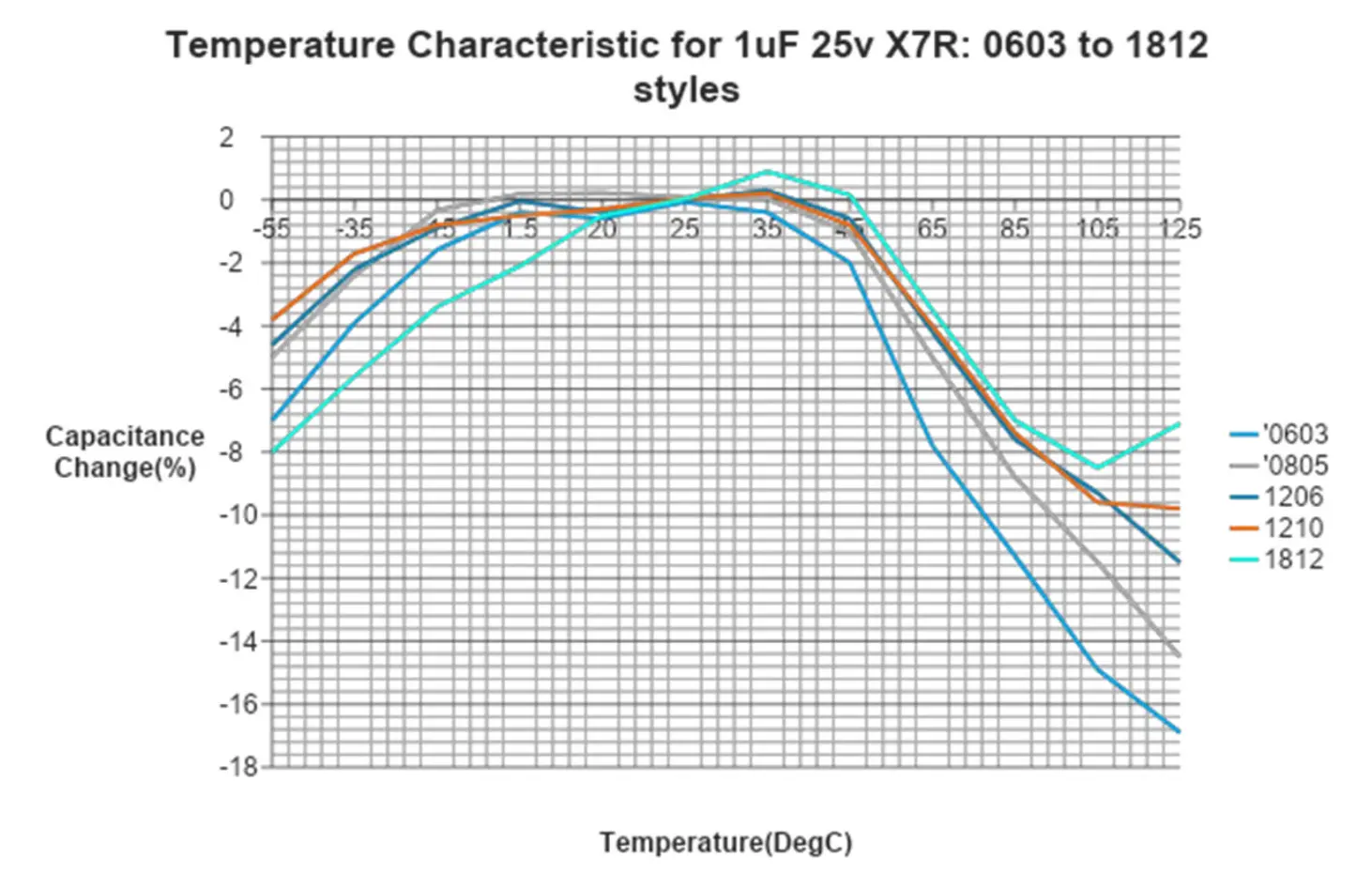
Similar trends are seen when looking at the temperature performance of size reduced MLCC’s. The figure below demonstrates how for the same capacitance, a 0603 package loses nearly double the effective capacitance compared to an 1812 package at high temperatures.

Temperature Characteristic for 1uF 25v X7R: 0603 to 1812 styles

The story doesn’t end there. Miniaturization of capacitors has a deleterious effect on numerous other performance parameters, including ripple current handling capability, ESD protection, and electrical strength. Many of these weaknesses are particularly noticeable in high voltage and high power applications. Of greater concern than the performance tradeoffs is the potential for failure over time, especially in safety-critical systems.

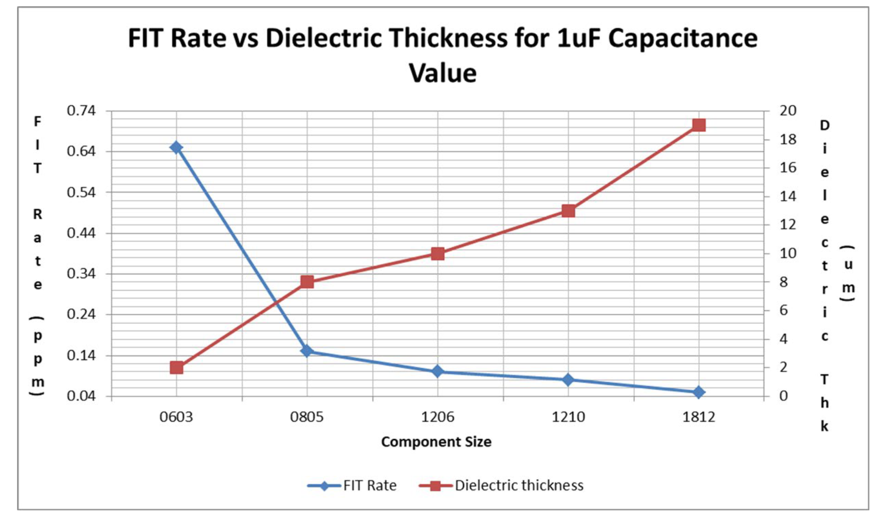
The following figure depicts the failure rate of a typical one microfarad capacitor compared to its dielectric thickness, which is directly correlated to package size. As the size moves from 1812 to 0603, the failure rate increases by more than an order of magnitude.

Miniaturization Tradeoffs

Manufacturing techniques and material technologies have pushed the envelope of achievable capacitance density further, yielding incredibly compact circuits at very attractive price points. This trend will undoubtedly continue, and in most cases, with little overhead to the design cycle. However, in specific applications, aggressive miniaturization is accompanied by nuanced performance tradeoffs that can greatly hinder a product’s success. Increased voltage dependence, temperature sensitivity, and electrical strength are a few discussed above. If the designer is not at least aware of what these tradeoffs are and when they matter, the downstream effects of poor manufacturing yield, field failures, and warranty returns can quickly overtake the potential success of any product.

pdf version of the paper is available from AVX website link below

Related

Source: AVX

Recent Posts

RF Inductors: Selection and Design Challenges for High-Frequency Circuits

10.11.2025
24

Transformer Safety IEC 61558 Standard

7.11.2025
8

ESR of Capacitors, Measurements and Applications

7.11.2025
40

3-Phase EMI Filter Design, Simulation, Calculation and Test

6.11.2025
48

KYOCERA AVX Releases Antenna for Iridium Satellite IoT Applications

6.11.2025
11
Image credit: Samtec

How to Match the Right Connector with Protocol Requirements

6.11.2025
13

Smoltek CNF-MIM Capacitors Pass 1,000h Reliability Test

6.11.2025
12

Capacitor Lead Times: October 2025

6.11.2025
66

Paumanok Unveils Aluminum Capacitor Foils World Markets Study 2025-2030

6.11.2025
14

Upcoming Events

Nov 11
17:00 - 18:00 CET

Industrial Applications Demand More from Interconnects in Next-Gen Designs

Nov 12
11:00 - 12:00 CET

PCB Design: Impedance is for everyone!

Nov 12
November 12 @ 12:00 - November 13 @ 14:15 EST

Microelectronic Packaging Failure Modes and Analysis

View Calendar

Popular Posts

  • Buck Converter Design and Calculation

    0 shares
    Share 0 Tweet 0
  • Boost Converter Design and Calculation

    0 shares
    Share 0 Tweet 0
  • LLC Resonant Converter Design and Calculation

    0 shares
    Share 0 Tweet 0
  • Flyback Converter Design and Calculation

    0 shares
    Share 0 Tweet 0
  • Ripple Current and its Effects on the Performance of Capacitors

    3 shares
    Share 3 Tweet 0
  • MLCC and Ceramic Capacitors

    0 shares
    Share 0 Tweet 0
  • Dual Active Bridge (DAB) Topology

    0 shares
    Share 0 Tweet 0
  • What is a Dielectric Constant and DF of Plastic Materials?

    4 shares
    Share 4 Tweet 0
  • SEPIC Converter Design and Calculation

    0 shares
    Share 0 Tweet 0
  • Flying Capacitors

    0 shares
    Share 0 Tweet 0

Newsletter Subscription


Passive Components Blog

© EPCI - Leading Passive Components Educational and Information Site

  • Home
  • Privacy Policy
  • EPCI Membership & Advertisement
  • About

No Result
View All Result
  • Home
  • Knowledge Blog
  • PCNS

© EPCI - Leading Passive Components Educational and Information Site

This website uses cookies. By continuing to use this website you are giving consent to cookies being used. Visit our Privacy and Cookie Policy.
Go to mobile version