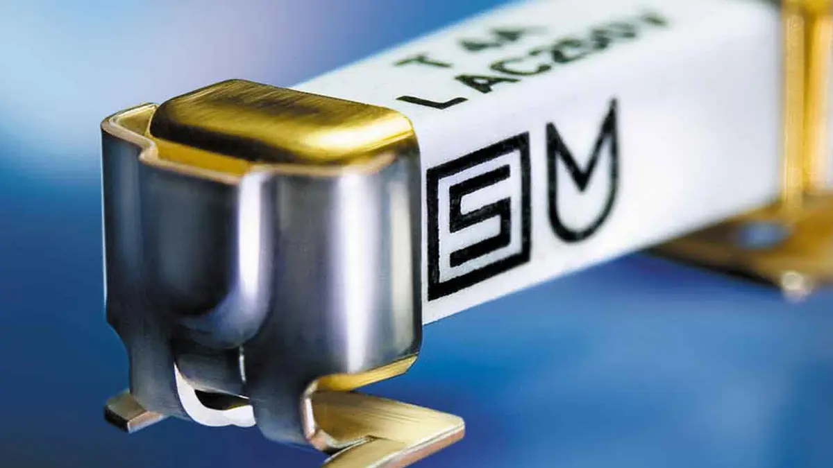
Bill Schweber in article published by Electronic Design describes the basics of powers supply protection and difference between the protection components.
Protecting a power supply and its load from each other’s faults requires components and functions such as the fuse, undervoltage lockout, crowbars, and clamps.
Power protection is like insurance: You pay for it, yet hope you don’t need it. But it’s not a simple “purchase.” The first protection question is, “What am I seeking to protected, and against what event(s)?” The answer is two-fold: the supply and its components need protection from load faults, while the load needs protection against supply faults.
The second question is, “What kinds of faults?” These can be excessive current or voltage, ranging from a short circuit and the associated high currents, to transients and voltage spikes due to ESD (electrostatic discharge) or even lightning. Some faults are due to component failure, where others can be due to a wiring mistake. Finally, in some cases, the fault mode can even be a supply voltage that’s too low.
The components that must be added to a circuit or system to provide circuit protection receive little appreciation. They don’t enhance the functionality, nor do they add to the glamour, appeal, or performance of the product. They take up space, add cost, complicate the bill of materials (BOM), and usually sit quietly without doing anything. That’s the situation until they’re needed, when they’re expected to quickly react and protect other components in the circuit from malfunction or even destruction.
Protecting against any and all possible power problems is complex, costly, and generally unneeded. It’s the role of the design engineer to assess whether fault protection is needed; after all, there’s little reason to protect a smartphone against power-rail spikes caused by lightning.
There are many protection-related components and techniques to choose from. Most are passive, but some are active. This article will focus only on the passive or mostly passive types.
As with most design issues, overlapping perspectives exist on the same basic topic. For power protection, you can look at it first in terms of potential fault conditions and then the options for dealing with them, or in terms of the various protection components and then the faults for which they’re used. A circuit or system may use one or multiple levels and types of protection. Many of these protection features are built into the power supply, whether it’s a dc-dc converter IC or a larger ac-dc unit. In other cases, such as when an engineer is designing a supply from individual components, some of them may need to be added.
It Begins with Overcurrent and Fuses
Whether a result of a short circuit external to the supply or within it, overcurrent is a major concern. It can initiate a cascade of additional failures, put users at risk, and even start a fire. The oldest solution is a fuse (also called a fusible link) (Fig. 1) with apparently simple operation: when the current flow exceeds the fuse’s current threshold, the current causes the special wire within the fuse to overheat (I2R heating), melt, and open, thus cutting the current to zero.
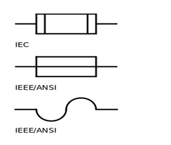
Once the fuse blows open, the current flow is completely cut off, and can be restored only by replacing the fuse itself, which is either a benefit or a negative, depending on the application. The more-complex circuit breaker is an alternative to the fuse which doesn’t need replacement after activation. Some breakers are thermally activated, some are magnetically activated; either way, like the fuse, the breaker is a current-triggered device.
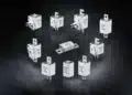
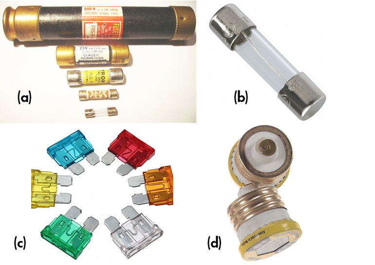
Although the fuse is “ancient,” it’s inexpensive, reliable, easy to design in, and effective. Basic fuses are available with ratings under 1 A to hundreds of amps (Fig. 2). While fuses do have a voltage rating, that’s primarily for contact rating and physical spacing, as the fuse itself is triggered only by the current through it and not the voltage.
For some devices, the fuse isn’t a good choice (think of a smartphone’s limited-energy internal power circuits), while it’s the best choice in others, and often used in conjunction with other protection techniques. The fuse is frequently added to help a product meet regulatory safety requirements, due to the directness of its functionality.
Note that despite their simple principle, they’re offered in many variations and subtleties, such as how long it takes for it to react and open the circuit (which is a function of both the current and elapsed time). Fuse datasheets have many charts showing performance under various conditions, and specialty fuses are available for unique situations.
Undervoltage Lockout (UVLO)
UVLO ensures that a power-supply (or dc-dc) converter doesn’t attempt to operate when its own input voltage is too low (Fig. 3). This is done for two reasons. First, circuitry within the supply or converter may malfunction or act in an indeterminate way if the input dc voltage is too low, and some higher-power components may actually be damaged. Second, it prevents the supply/converter from drawing on primary power if it can’t produce valid output power.

To implement UVLO, a small, low-power comparison circuit within the supply/converter compares the input voltage to a preset threshold and puts the unit into quiescent mode until the threshold is crossed. To ensure that the UVLO doesn’t “chatter” around the threshold, a small amount of hysteresis is added.
Overvoltage Protection (OVP)
Although a supply or power converter is designed to normally produce a fixed dc-output voltage, an internal failure in the supply may cause this voltage to rise, and possibly damage the load to which the supply is connected. OVP is a function that monitors the supply/converter output versus an internal reference and short-circuits that output if the voltage rises above the threshold. The OVP must do several things:
- Obviously, prevent any excessive voltage from appearing at the protected components.
- Not interfere with normal operation, but instead be “invisible” to the power supply.
- Distinguish between normal transient voltage fluctuations and excessive overvoltage.
- Be fast, and respond before the load is damaged when a genuine overvoltage situation does occur.
- Not have false positives (false trips), which are a nuisance, and not fail to respond to real overvoltage conditions.
The Crowbar
One widely used OVP function is the “crowbar,” supposedly so named because it has the same effect as placing a metal crowbar across the output and thus shorting the output voltage. There are two kinds of crowbars: one where the crowbar, once tripped, will only be reset if the power is turned off; and one where it will reset itself once the fault is cleared. The second one is useful when the condition that tripped the crowbar is due to some sort of transient rather than a hard failure in the supply. While most supplies now come with a built-in crowbar, many vendors offer a small, separate crowbar circuit that can be added to an existing supply if needed.
The crowbar is a normally high-impedance circuit across the supply output (or input of the load to be protected) (Fig. 4). It transforms into a low-impedance circuit when an overvoltage situation occurs and triggers it, and it stays in low-impedance mode until the current decreases below the “holding current.” Subsequently, it returns to the high-impedance, normal-operation state. The crowbar must be able to handle the current flowing through it during the time the supply is in overvoltage state.

Other common crowbars are based on thyristor surge protectors (TSPs). These are silicon-based PNPN devices with a breakdown voltage that can be set precisely by their manufacturer. TSPs are offered in many package types and can dissipate various levels of surges.
There’s also the gas discharge tube (GDT), which is a miniature spark gap usually housed in a ceramic enclosure and PCB-compatible. When triggered by a high voltage, the spark gap conducts and all current flow is diverted. Spark gaps can be manufactured so that they protect from modest voltages (around 100 V) to thousands of volts. When the overvoltage situation clears, the TSP or GDT go back to normal, high-impedance mode.
The Clamp
A complement to the crowbar is the clamp, which prevents the voltage from exceeding a preset level. Clamps are often referred to as transient voltage suppressors (TVSs), since they may be protecting against a startup transient or inductive transient rather than an actual failure (Fig. 5). For most clamps, the clamp function releases when the overvoltage condition clears.
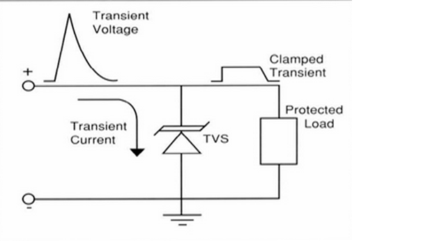
A clamp conducts just enough current to maintain the voltage across it at a safe, desired value when the transient is above the clamp’s conduction voltage. It must be rated for the power it will have to dissipate for a specific time, usually a relatively short transient event. The TVS clamp—a silicon bipolar junction device similar to a basic rectifier diode but designed to survive reverse breakdown-voltage situations—is available with breakdown voltages from 4 to 500 V, and in various power ratings to provide different surge-protection capabilities. A TVS is a bipolar junction device.
Compared to a clamp, the crowbar’s low holding voltage lets it carry higher fault current without dissipating much power, so that it can handle higher currents and do so for longer periods (Fig. 6). It’s also easier to configure the circuit so that the crowbar also causes a fuse to blow (and thus stop current flow completely), if that’s desired.

A clamp can also be built using a metal-oxide varistor (MOV), a bidirectional semiconductor voltage-transient suppressor device. It conducts (i.e., switches) at a voltage related to the size and number of special grains between its leads. MOV breakdown voltages range from about 14 V to over a 1,000 V, with the larger ones intended to handle several kilovolt-amps (kVA), such as from a lightning surge.
MOVs are low cost, fast acting, easy to use, and offered in many voltage ratings, and their own failure mode is to short circuit (which is preferred in most fail-safe designs). However, they can only dissipate small amounts of power, so they’re suited only for short-term and transient OVP situations
In general, crowbars are better for long-term faults, while clamps are best suited for transient events rather than outright supply failures. Many commercial power supplies incorporate both a crowbar and a clamp. If the concern is outright failure and associated high-current flow, which would soon overwhelm the dissipation rating of the crowbar or clamp, the design should also include a fuse or circuit breaker. The fuse/breaker will eventually blow from the overcurrent related to the excess voltage and thus provide multi-factor protection.
Don’t Forget Thermal Protection
Finally, there’s the issue of thermal-overload protection. By its nature, any power supply generates heat because it’s less than 100% efficient, and even an efficient supply generates a potentially troublesome amount. For example, a 100-W supply that’s 90% efficient still dissipates 10 W, which is very capable of warming up a small, sealed enclosure. For this reason, the supply must be designed with sufficient active cooling (e.g., via a fan) or passive cooling (achieved by convection air flow and conductive cooling paths).
But what happens when the fan fails, the air-flow path is blocked, or another heat source is introduced into the enclosure? The supply may exceed its temperature rating, which shortens its life and may even cause immediate malfunction. The solution is a sensor within the supply (as a discrete device or incorporated within an IC) that senses the ambient temperature and puts the supply into a quiescent mode if it exceeds a preset limit. Some implementations allow the supply to resume operation if the temperature drops, while others do not.
Power-supply protection is, not surprisingly, a nuanced topic. There are issues of current, voltage, and power handling, dissipation by the protection circuit or components, and fault duration, as well as protection component placement, cost, and footprint. But protection is also good engineering practice and often mandated by regulatory standards. Again, it’s like insurance: It comes in many forms and covers many types of bad events. You hope you don’t need it, but there’s a chance you will for a variety of possible reasons.
featured image: Schurter
References
- Microsemi Corp., MicroNote 106, “Crowbars and Clamps: What Are Their Major Differences?”
- Sunpower Electronics Ltd., “What is Over Voltage Protection?”
- Bourns Inc., “Transient Overvoltage Protection
- Texas Instruments SLVA769, “Understanding Undervoltage Lockout in Display Power Devices”
- Gursimran Singh Chawla, Chameli Devi School of Engineering, “Fuses and Its Type in Power System”