Passive Components Blog
No Result
View All Result
  • Home
  • NewsFilter
    • All
    • Aerospace & Defence
    • Antenna
    • Applications
    • Automotive
    • Capacitors
    • Circuit Protection Devices
    • electro-mechanical news
    • Filters
    • Fuses
    • Inductors
    • Industrial
    • Integrated Passives
    • inter-connect news
    • Market & Supply Chain
    • Market Insights
    • Medical
    • Modelling and Simulation
    • New Materials & Supply
    • New Technologies
    • Non-linear Passives
    • Oscillators
    • Passive Sensors News
    • Resistors
    • RF & Microwave
    • Telecommunication
    • Weekly Digest

    SEPIC Converter with Coupled and Uncoupled Inductors

    Coupled Inductors in SEPIC versus Flyback Converters

    Vishay Releases High Current 3.3 V to 36 V ESD Protection Diodes

    TDK Extends SMT Gate Drive Transformers to 1000 V

    Non-Linear MLCC Class II Capacitor Measurements Challenges

    Researchers Demonstrated HfO Anti-Ferroelectric Flexible Capacitors

    Connector Industry Achieves Double-Digit Growth

    Stackpole Unveils Metal Element High Current Chip Jumpers

    Common Mistakes in Flyback Transformer Specs

    Trending Tags

    • Ripple Current
    • RF
    • Leakage Current
    • Tantalum vs Ceramic
    • Snubber
    • Low ESR
    • Feedthrough
    • Derating
    • Dielectric Constant
    • New Products
    • Market Reports
  • VideoFilter
    • All
    • Antenna videos
    • Capacitor videos
    • Circuit Protection Video
    • Filter videos
    • Fuse videos
    • Inductor videos
    • Inter-Connect Video
    • Non-linear passives videos
    • Oscillator videos
    • Passive sensors videos
    • Resistor videos

    SEPIC Converter with Coupled and Uncoupled Inductors

    Coupled Inductors in SEPIC versus Flyback Converters

    Non-Linear MLCC Class II Capacitor Measurements Challenges

    Percolation Phenomenon and Reliability of Molded Power Inductors in DC/DC converters

    Root Causes and Effects of DC Bias and AC in Ceramic Capacitors

    How to Calculate the Output Capacitor for a Switching Power Supply

    Switched Capacitor Converter Explained

    Understanding Inductor Dot Markings and Their Application in LTspice

    Accelerating Full Bridge LLC Resonant Converter Design with Frenetic AI

    Trending Tags

    • Capacitors explained
    • Inductors explained
    • Resistors explained
    • Filters explained
    • Application Video Guidelines
    • EMC
    • New Products
    • Ripple Current
    • Simulation
    • Tantalum vs Ceramic
  • Knowledge Blog
  • Suppliers
    • Who is Who
  • Events
No Result
View All Result
Passive Components Blog
No Result
View All Result

Pulse Expands its Range of Ultra-low DCR Power Bead Inductors for Computing & Storage

16.9.2022
Reading Time: 3 mins read
A A

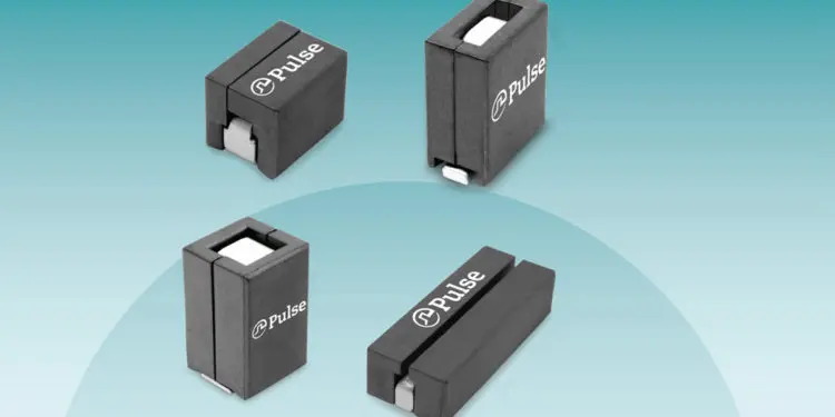
Pulse expands its range of power bead inductors with the introduction of six new platform sizes designed for the latest multi-phase and PoL architectures for server, graphics and high power FPGAs.

The latest platforms have ultra-low DCR, low loss ferrite cores and an optimized structure to ensure that they offer the highest efficiency and enable maximum power density.

RelatedPosts

Pulse Electronics Releases High Current, Low DCR Inductors in Compact Size

NIC Components Extends SMD High Voltage MLCC Offering

Stackpole Offers RoHS Compliant Lead-Free Thick Film Chip Resistors

The platforms range in size from 5.7×5.5mm to 10.8×8.2mm and come in inductances from 50nH to 1uH with peak current capability exceeding 120A and DCR as low as 120uOhms.

Part  Number SeriesFootprint (mm Max)  Height (mm Max)DCR (mOhms)Inductance RangePeak Current
PA40595.7 x 5.54.60.20050-70nH50Apk
PA50417.2 x 6.711.20.290120-330nH89Apk
PA499010.0 x 6.012.00.12080-330nH178Apk
PG17129.6 x 6.49.30.170150-300nH75Apk
PA498710.0 x 7.012.00.810470-1000nH32Apk
PA518710.8 x 8.28.20.120100-200nH100Apk

“Pulse has long been a leader in power magnetics for computing and storage applications and these latest offerings add to the already significant portfolio of our high-volume, cost-optimized products.  Our superior product, fast-turn prototyping and end-customer relationships enable us to maintain our leadership position”. John Gallagher | Product Marketing, Power PBU, Pulse Electronics

Although power beads can be used in a wide-range of applications, including input filters and single phase point of load (PoL) regulators, the most common implementation is as the energy storage element in a high-current multi-phase buck regulator. In these applications it is required to convert an input voltage (12v or 48v) down to relatively low output voltage (0.8 to 1.8v) but at currents that can change from 0A to 500Apk in a few hundred nanoseconds.

To protect the sensitive devices being powered these applications also require the output voltage to be very stable which necessitates minimizing the output ripple current. A single phase solution could be enabled but the ability to respond quickly (which requires a low apparent inductance) would be in direct opposition to the need for voltage stability (which requires a high apparent inductance).

By implementing a multi-phase topology, one avoids this conflict by breaking the current into multiple parallel paths. Each path has its own inductor and each path is activated (turned on/off) at different times throughout the cycle before being recombined at the output. This out-of-phase operation means that the ripple current in one path is increasing while in the other paths it is decreasing such that the ripple current partially cancels resulting in low output ripple.

The fact that there is ripple current cancelation at the output allows the inductance in each path to be significantly lower (50-250nH) and this in turn enables a much faster transient response.

These operational benefits of a multiphase circuit come at the expense of putting increased stress on the inductor.  Although the output ripple current is drastically reduced, the ripple current in each phase, due to the low inductance, is very high. 

If the inductor is not optimized the high ripple current will lead to excessive AC core loss and AC winding loss. In addition, the relatively low ratio of output voltage to input voltage (10%) means that the inductor effectively sees a much higher operating frequency which also contributes to high AC losses. Fortunately, Pulse is able to  leverage our three-dimensional finite element analysis modelling skills, in depth material knowledge and vast design experience to ensure we optimize the design to minimize the AC and DC losses.

Related

Source: Pulse Electronics

Recent Posts

SEPIC Converter with Coupled and Uncoupled Inductors

26.8.2025
1

Coupled Inductors in SEPIC versus Flyback Converters

26.8.2025
6

Vishay Releases High Current 3.3 V to 36 V ESD Protection Diodes

25.8.2025
11

TDK Extends SMT Gate Drive Transformers to 1000 V

20.8.2025
20

Stackpole Unveils Metal Element High Current Chip Jumpers

19.8.2025
33

Common Mistakes in Flyback Transformer Specs

15.8.2025
40

Vishay Releases Miniature SMD Trimmers for Harsh Environments

14.8.2025
15

Littelfuse Unveils High-Precision TMR Angle Magnetic Sensors

13.8.2025
12

Stackpole Extends Voltage of High Temp Chip Resistors

13.8.2025
11

High Voltage MLCCs Meeting the Growing Demand for Efficiency in Power Conversion

12.8.2025
151

Upcoming Events

Aug 27
17:00 - 18:00 CEST

Capacitor Assemblies for High-Power Circuit Designs

Sep 3
15:30 - 17:30 CEST

How to Choose Your Magnetic Supplier

Sep 16
17:00 - 18:00 CEST

EMI Shielding Challenges

Sep 22
September 22 @ 13:00 - September 25 @ 15:15 EDT

Pre Cap Visual Inspection per Mil-Std-883 (TM 2017)

Sep 30
September 30 @ 12:00 - October 2 @ 14:00 EDT

MIL-Std-883 TM 2010

View Calendar

Popular Posts

  • Buck Converter Design and Calculation

    0 shares
    Share 0 Tweet 0
  • Boost Converter Design and Calculation

    0 shares
    Share 0 Tweet 0
  • Flyback Converter Design and Calculation

    0 shares
    Share 0 Tweet 0
  • LLC Resonant Converter Design and Calculation

    0 shares
    Share 0 Tweet 0
  • What is a Dielectric Constant and DF of Plastic Materials?

    4 shares
    Share 4 Tweet 0
  • Ripple Current and its Effects on the Performance of Capacitors

    3 shares
    Share 3 Tweet 0
  • Dual Active Bridge (DAB) Topology Explained

    0 shares
    Share 0 Tweet 0
  • How to Design an Inductor

    0 shares
    Share 0 Tweet 0
  • Core Materials, Permeability and Their Losses

    0 shares
    Share 0 Tweet 0
  • MLCC Case Sizes Standards Explained

    0 shares
    Share 0 Tweet 0

Newsletter Subscription


Passive Components Blog

© EPCI - Leading Passive Components Educational and Information Site

  • Home
  • Privacy Policy
  • EPCI Membership & Advertisement
  • About

No Result
View All Result
  • Home
  • Knowledge Blog
  • Premium Suppliers

© EPCI - Leading Passive Components Educational and Information Site

This website uses cookies. By continuing to use this website you are giving consent to cookies being used. Visit our Privacy and Cookie Policy.
Go to mobile version