


source: H.C. Starck Tantalum and Niobium GmbH; ESA SPCD 2018 Symposium
EPCI e-symposium library article
Ta capacitors are the best choice when applications require highest capacitance (energy density) on miniature scale combined with high reliability, low ESR, and excellent stability over wide ranges of time and application temperature.
Recently, the demand of high reliability capacitors withstanding harsher conditions especially with respect to higher application voltage has been increased. Main driver for such applications are besides aviation and aerospace also automotive (driver assistance systems, e-vehicles) and transportation, medicine (defibrillators), defense but also consumer electronics like for data storage (solid state drive-SSD).
H.C. Starck continuously improves its portfolio of high voltage powders allowing to expand the tantalum capacitor technology to new fields of application. The “High Voltage Medium Capacitance” (HVMC) powders have a uniquecombination of structural homogeneity, high purity and tailored pore structure to provide the highest capacitance of Ta powder for the formation voltage (Vf) range >80 Vf. We will show the latest status of new developed powders that extend the range of forming voltage to 300 V and even up to 400 V.
Moreover, new options to further improve the pore structure resulting in increased capacitance at a given forming voltage will be presented as well. Beyond powder design, the tremendous impact of anode processing to master such high anodization voltages is highlighted.
published by EPCI under approval of ESA SPCD 2018 organizing committee.
Title:Pushing Tantalum capacitors to the limit: A powder manufacturers view to 300 V anodizations and beyond
Author(s): Marcel Hagymási, Ralph Dietmar Otterstedt, Christoph Schnitter, Oliver Thomas, Rich Reifenheiser
Organisation(s): H.C. Starck Tantalum and Niobium GmbH Im Schleeke 78-91, 38642 Goslar, Germany
Symposium: ESA SPCD 2018
Reference: Materials and Processes 3.
ISBN: N/A
e-Sessions Applications: Aerospace, Automotive, Industrial, Medical
e-Sessions Scope Components: Capacitors
e-Sessions Topics: Technology, Materials
INTRODUCTION
Moore’s law predicts that the number of transistors in a dense integrated circuit doubles about every two years [1]. This law describes the impressive speed of miniaturization but also the performance increase of electronic parts that has until now never stopped. Likewise, the performance of tantalum capacitors is continuously improved but with a slower pace. For high voltage applications an unceasing and increasing demand for powders optimized for applications voltages >35 V is observed.
They are used for different fields of application, often connected with high reliability: consumer electronics (SSD, charging devices, etc.), transportation and automotive, signal transmission for railway, medical devices (e.g. implantable cardioverter defibrillators), defense and aerospace (planes, satellites).
There are in general different trends that we have realized in recent years:
- Demand for more stored charge in a given volume at a given voltage, e.g. more capacitance at 150 V forming voltage not reachable with standard Ta powders to create new capacitor types for new applications.
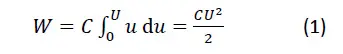
- Demand to further increase the forming voltage above 300 V since the energy W that can be stored by a capacitor is correlated with the voltage U squared:
 HVMC powders provide the required capacitance at forming voltages in the range of 100-350 V and are compared to standard tantalum capacitor powders, as shown in fig.1. At any voltage in this range, there is at least one powder type that has more capacitance and energy density than comparable standard powder types. It was already shown that the key for the excellent high voltage ability of HVMC powders is the improved microstructural homogeneity with respect to pore and primary particle sizes [2, 3].
The tighter primary particle distribution allowing higher capacitance is the result of extensive research to optimize the parameters of our production processes. We have developed different HVMC powder types, since each anodization voltage has its own optimum concerning primary particle and pore size distribution. To simplify the powder naming we have decided to put the classification (“HV” = High Voltage) and the recommended optimum forming voltage in its name (like HV200 – developed for 200 Vf) in contrast to the conventional naming where the capacitance (mostly measured at lower voltages) is included.
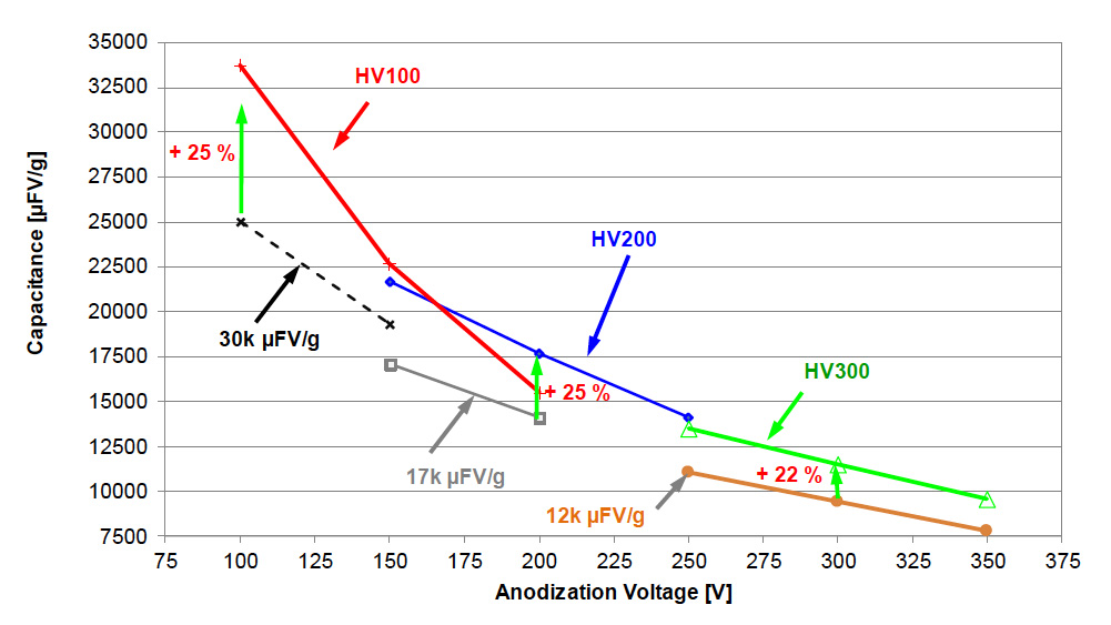
Fig.1 Capacitance as a function of forming voltage of HV100-HV300 in comparison to standard Na reduced powders.
The purpose of this paper is to show our general approach how to improve the microstructure regarding higher capacitance at a given formation voltage exemplified by our newly developed HV150 powder and how to extend the range of anodization up to 400 V by referring to our latest development, the HV400 powder. The impact of the anodization technique when reaching 400 V is significant and has, like the powder itself, to be optimized to realize new types of capacitors in the future.
How to provide more capacitance by tailoring the microstructure?
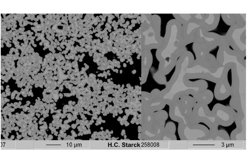
The microstructure of the tantalum powder is the key for realization of higher volumetric capacitances and must be tailored for each anodization voltage range to its optimum [2]. Currently, new capacitors with anodization voltage of ~150 Vf are highly requested. At 150 V anodization our products HV100 and HV200 show nearly comparable capacitance in electrical wet tests (see fig.2). However, due to its smaller pores as shown in fig. 3, capacitors made from HV100 will show worse impregnation and ESR behavior compared to those made from HV200 having larger pores. That’s why HV200 wouldhave been the powder of choice for 150Vf in the past.
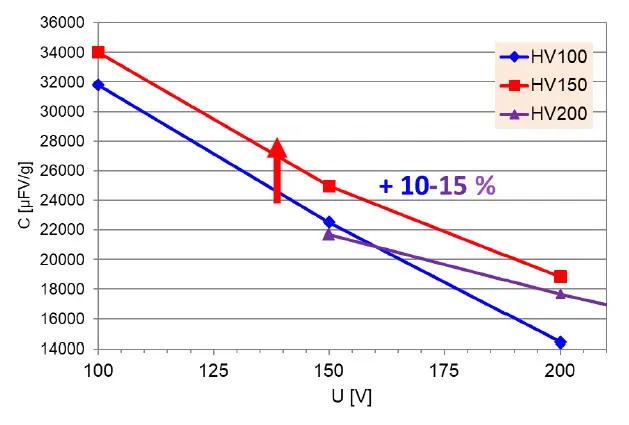
Fig. 2 Capacitance of different HV powder for the anodization voltage range of 100-200 V (@60°C forming bath temperature).
Our task was to develop a powder with distinctly higher capacitance than the HV100 and HV200 products in the range Vf=100-200 V by improving the particle and pore size distribution of the powders. To achieve this the Mg reduction process, proprietary to H.C. Starck and key step of the HVMC powder production route, needed to be enhanced. The pore size distribution of sintered anodes is considered as a suitable evaluation method because it demonstrates the influence of the pressing and sintering step on the powder structure.
…..
The next generation of high(est) voltage powder: HV400
Our HV300 product is mainly used for anodization voltages in the range of 250-300 Vf and is approved as a powder for highest reliability applications like medical and aerospace. It was proven by capacitor manufacturers that this is the tantalum powder enabling capacitors with the highest energy density currently available.
The target of further increasing the energy density according to equation (1) was the driving force for the development of an HV400 that can be anodized up to 400 V. Therefore, again the powder microstructure must be adapted: both, primary particle size as well as the medium pore size must be increased.
The higher anodization voltage will “consume” more tantalum that is converted toTa2O5 film which in turn needs more space than a film formed at 300 Vf. A direct comparison of the pore structure of anodes made from HV300 and HV400 powders with identical pressing and shrinkage conditions can be seen in fig 4. The maximum of the primary pore peak has been shifted from 1200 nm to 1600 nm while the secondary pore peak position has no significantly change. Main difference is that the pore size distribution of anodes made from the new HV400 powder is narrower than that of anodes made from HV300 powder – primary and secondary peak position are closer, the distribution is “less” bimodal.


Fig. 4 Pore size distributions of anodes made from HV300 (green) and HV400 (red) powder (Press density 5,5 g/cm3, 10 % shrinkage)
Anodes of both HVMC powders were used for anodization from 250 to 400 V with the same formation program. At 250 Vf, the HV300 powder has a slightly higher capacitance, but for voltages above 260 V the HV400 has a higher capacitance (fig. 5). At 400 Vf anodes made from HV400 powder show 9550 CV/g, an increase by 20 % when compared to those made from HV300 powder. The slope of the HV400 capacitance curve is less steep than that of the HV300 – meaning it is more stable and could be used for even higher anodization voltages.
… read more at the full paper below…
CONCLUSION
We have presented the latest development of our HVMC high voltage tantalum powders that provide highest capacitance due to their improved microstructural homogeneity when compared to current standard powders. The newly developed HV150 powder provides a further capacitance increase up to 15 % at 150 Vf anodization by optimization of the primary particle and anode pore size structure.
The primary pore peak is much narrower and higher compared to that of our HV100 and HV200 products. Moreover, the secondary pore peak is very close to the primary pore peak. Improved homogeneity is the key for future powder developments enabling even higher capacitance at high formation voltages.
We were also successful to further increase homogenously the primary pore and particle size distribution by adjusting our process resulting in our new HV400 powder that extends the anodization range for tantalum powders from currently 300 V to 400 V allowing to store even more energy in a given size.
We found that besides adjustment of the powder structure the anodization process must be adapted as well. We have shown that not only phosphorous, which was already known, but also carbon is incorporated significantly into the formed anodic oxide film. Both components are introduced by the used electrolyte system.
In contrast to former investigations reported in literature, this was to our knowledge the first time that such investigations on phosphorus contents of high voltage anodes with nodular structure anodized under typical high voltage up to 250 Vf conditions are reported.
Nevertheless, finding a “perfect” anodization program incombination with a “perfect” anodization bath preventing the incorporation of critical amounts of foreign ions remains a task to be followed up in the future.
REFERENCES
[1] G. E. Moore “Cramming more components onto integrated circuits”. Electronics. Band 38, Nr. 8, 1965, 114–117
[2] M. Hagymási, H. Haas, C. Schnitter, H. Brumm, ”High Voltage Tantalum Powder – Challenges andOpportunities for new Powder Generation”, CARTS Europe, Nice, France 2011 CARTS Nice .
[3] M. Hagymási, C. Schnitter, R. Reifenheiser, O. Thomas, “Highest capacitance at higher voltages: Pushing the limits of tantalum high voltage capacitors” 2nd SPCD, Noordwijk, Netherlands 2016.
[4] Donald H. Stephenson, Martin D. Cymerman, Barry C. Muffoletto, “Using aqueous electrolyte containing ethylene glycol or polyoxyethylene glycol and phosphoric acid”, US6231993 B1, 29. Sept. 1999
[5] D. M. Smyth, T. B. Tripp, G. A. Shirn, “The Heat‐Treatment of Anodic Oxide Films on Tantalum IV. Anodization in Phosphoric Acid Solutions”, J. Electrochem. Soc. 1966 Vol. 113, issue 2, 100-104
[6] Q. Lua, S. Matoa, P. Skeldona, G.E. Thompsona, D. Mashederb, H. Habazakic, K. Shimizu, “Anodic film growthon tantalum in dilute phosphoric acid solution at 20 and 85 °C”, Electrochimica Acta, Vol. 47, Issue 17, 2002,p. 2761–2767.
[7] Herman A. Johansena, George B. Adams Jr., Pierre Van Rysselbergheb, “Anodic Oxidation of Aluminum,Chromium, Hafnium, Niobium, Tantalum, Titanium, Vanadium, and Zirconium at Very Low Current Densities”,J. Electrochem. Soc. 1957 Vol. 104, issue 6, 339-346
[8] M. Fernández, J. Baonza, J. M. Albella and J. M. Martínez-Duart, “Influence of electrolytes in the electrical characteristics of anodic films on tantalum“, Electrocomponent Science and Technology, 1981, Vol. 7, pp. 205- 210
[9] D. Gerstemberg, “Handbook of Thin Film Technology”, chapter 19, Ed. L. I. Maissel and R. Glang, McGraw- Hill, N.Y. (1970).
[10] K. Shimizu, K. Kobayashi, G. E. Thompson, P. Skeldon, G. C. Wood, “Anodic oxide films on tantalum:incorporation and mobilities of electrolyte-derived species “, Philosophical Magazine B, 1996, Vol 73, N0.3, 461-485
[11] I. Montero, J. M. Albella, J.M. Martinez-Durat, L. Soriano, „Dielectric and Structural characteristics of Ta2O5anodic films formed in phosphoric acid electrolytes “, J. of Materials Science “” (1987), 1785-1789
[12] C.J. Dell’Oca, L. Young, “Ellipsometric studies of anodic oxide films formed on tantalum in diluted phosphoric acid”, J. Electrochem. Soc., Vol. 117 (12), 1970, 1545-1547
[13] G. Amsel, C. Cherki, G. Feuillade, J.P. Nadai, “The influence of the electrolyte on composition of anodic oxide films’ on tantalum”. J. Phys. Chem. Solids, Vol. 30, 1969, 2117-2134
[14] K. Shimizu, G.M. Brown, H. Habazaki, K. Kobayashi, P. Skeldon, G.E. Thompson, G.C. Wood, “Direct observation of anodic films formed on tantalum in concentrated phosphoric and sulfuric acid solution”, Corrosion Science, Vol. 40, No. 6, 1998, 963-973
[15] J. T. Kinard, B. J. Melody, D. A. Wheeler, P. M. Lessner, “Method and electrolyte for anodizing valve metals to high voltages”, Patent US 6,346,185 B1, Feb. 12, 2002
read the full technical paper in pdf here:
![]()
and presentation here:
![]()


