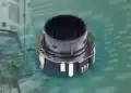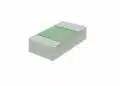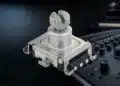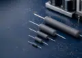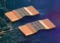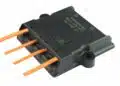







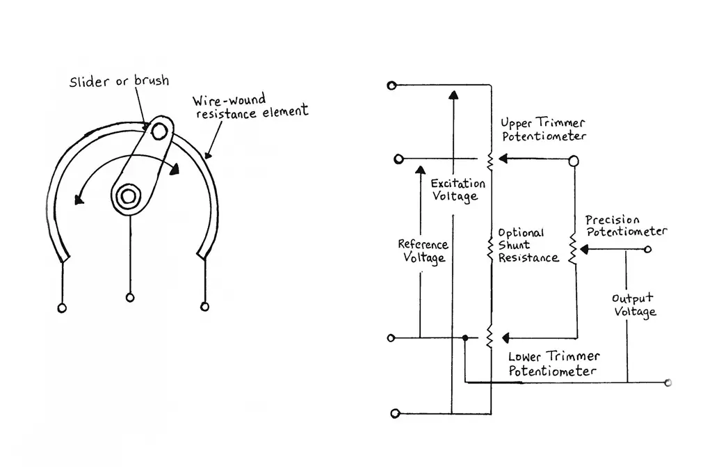
Variable resistors include Potentiometers, Rheostats and Trimmers that will be discussed in details in the following article.
Key Takeaways
- Variable resistors include potentiometers, rheostats and trimmers, combining a resistive element with mechanical motion and thus showing lower reliability than fixed resistors.
- Key behaviours are defined by resistance and travel concepts (Rtot, ER/EV, MR/MV, electrical vs mechanical travel, continuity travel) and by linearity/conformity, resolution and loading error.
- Noise and dynamic errors arise from contact effects (CRV, ENR, output smoothness), while mechanical parameters (play, runout, backlash) strongly influence hysteresis and stability.
- Type 2 power and panel‑mount potentiometers, Type 1 precision potentiometers and trimmers differ in materials, construction, accuracy and life, and all require proper wiper‑current and power derating to avoid wear, noise and overheating.
Introduction
Variable resistors are electromechanical components and therefore exposed not only to the weaknesses of fixed resistors but also to all the failure possibilities of electromechanics. Thus the reliability is comparatively poor.
The total resistance seldom is critical and usually follows the European E3 series or 1-2-5-10 (USA).
In practical electronics, several technologies can realize an adjustable resistance or position‑sensing function. The choice affects accuracy, lifetime, environmental robustness and interface complexity.
- Mechanical potentiometers and rheostats (rotary, linear, trimmers).
- Digital potentiometers (IC‑based electronically controlled resistors).
- Non‑contact position sensors (Hall, magnetoresistive, inductive, optical).
- Hybrid solutions combining mechanical pots with electronic linearization or digital readout.
In this article we first define key electrical and mechanical behaviours of variable resistors, then explain linearity, conformity, resolution and noise mechanisms, followed by construction and technology types for power and precision potentiometers, rheostats and trimmers. Finally, we introduce digital potentiometers and non‑contact position sensors and provide practical selection guidelines so that designers can choose an appropriate technology for user controls, calibration functions, power regulation and position feedback.
Digital potentiometers and electronic replacements
Digital potentiometers (often called “digipots”) integrate a resistor ladder and electronic switches in an IC package. They emulate a 2‑ or 3‑terminal potentiometer but are controlled by digital logic instead of a mechanical shaft.
Internally, a digital potentiometer consists of a series of equal or weighted resistors and MOSFET switches that connect the wiper node to one of the intermediate taps. The output resistance between terminals changes in discrete steps defined by the code written to the device.
- End‑to‑end resistance options typically range from a few kΩ up to several hundred kΩ.
- Resolution is expressed in bits (for example 8‑bit → 256 steps, 10‑bit → 1024 steps).
- Wiper resistance adds a small, code‑independent series resistance that must be considered in precision designs.
When replacing a mechanical potentiometer with a digital version, a few parameters dominate the selection process.
- End‑to‑end resistance and tolerance.
- Resolution (number of steps) and monotonicity.
- Wiper resistance and wiper current limits.
- Integral and differential non‑linearity over code.
- Supply voltage range and signal range (often limited to rails).
- Non‑volatile vs volatile memory for the last wiper position.
- Interface type (I²C, SPI, up/down, simple increment inputs).
Most modern digipots expose either a simple up/down control or a serial interface. Integration into a microcontroller system is straightforward and allows remote or automatic adjustment.
- Up/Down: clock and direction pins, suitable for simple push‑button adjustment.
- I²C or SPI: register‑based programming, supports multiple channels and stored configurations.
- Some devices integrate EEPROM or Flash to restore the last resistance value after power‑up.
Advantages and limitations vs mechanical potentiometers
Digital potentiometers remove moving parts and allow precise, repeatable adjustments under firmware control, but they are not drop‑in replacements in every application.
- Advantages: no mechanical wear, easy automation and calibration, small size, good matching between channels, simplified assembly.
- Limitations: restricted voltage range (often limited to supply rails), limited wiper current and power dissipation, discrete step resolution, sensitivity to ESD and transients.
Practical design considerations
In mixed‑signal designs digital potentiometers are typically used in low‑level network positions such as op‑amp feedback ratios, bias generators or sensor calibration loops instead of directly carrying high power. Their permitted signal range is commonly restricted to the supply rails of the IC, and exceeding specified wiper current or end‑to‑end power dissipation may cause non‑linearity, drift or long‑term damage. As a result it is usually better to place the digipot where only small currents flow and let a separate amplifier or power stage handle higher voltages or currents.
Many modern devices offer multiple channels, non‑volatile memory and integrated temperature or fault protection, which makes them attractive for factory calibration and remote adjustment in microcontroller‑based systems. In such cases the design should still respect ESD, latch‑up and EMC immunity limits and, in automotive domains, comply with the applicable AEC‑Q100 and functional safety requirements.
Non‑contact position sensors as potentiometer alternatives
In many industrial and automotive applications, mechanical potentiometers compete with non‑contact technologies that sense angle or displacement without a sliding contact. These solutions often deliver longer lifetime and better robustness against contamination.
Potentiometers within the position‑sensor family
In the broader position‑sensor landscape mechanical potentiometers represent the simplest resistive solution, while Hall‑effect, magnetoresistive, inductive and optical encoder technologies provide non‑contact operation with digital or analogue interfaces. Potentiometers continue to dominate low‑cost, moderate‑lifetime applications and analogue user controls, whereas Hall/GMR sensors, inductive position sensors and encoders are increasingly preferred in automotive, industrial automation, aerospace, medical and renewable‑energy systems where cycling, contamination and functional safety requirements are more demanding.
Position‑sensor technologies at a glance
| Technology | Contact | Lifetime & robustness | Interface | Typical domains |
|---|---|---|---|---|
| Mechanical potentiometer | Sliding contact on resistive track | 10⁴–10⁶ cycles; sensitive to wear, contamination and moisture. | Analogue voltage | User controls, simple feedback, low‑to‑medium cycling mechanisms. |
| Hall / GMR angle sensor | Non‑contact magnetic sensing | Essentially unlimited cycling; robust to shock, vibration and humidity; EMI must be managed. | Analogue, PWM or digital (SPI, SENT, I²C) | Automotive pedals, steering, industrial knobs, actuators. |
| Inductive position sensor | Non‑contact inductive coupling | High temperature capability and good contamination tolerance; suited for safety‑critical systems. | Typically digital or conditioned analogue | Automotive and industrial position sensing in harsh environments. |
| Optical encoder | Non‑contact optical disk and sensor | Very high resolution; sensitive to dust and condensation, but mechanically non‑wearing. | Digital quadrature or absolute code | Motor control, robotics, precision motion, CNC. |
Hall‑effect angle sensors
Hall‑effect sensors measure the magnetic field of a small magnet attached to a rotating shaft or moving element. Dedicated angle‑sensor ICs can decode the field vector into an absolute angle over 360°.
- No mechanical contact between sensor and shaft, enabling very high rotational life.
- Output options include analog voltage, PWM or digital interfaces (SPI, SENT, I²C).
- Common in throttle pedals, steering angle sensors, knobs and actuators in harsh environments.
Magnetoresistive and inductive sensors
Magnetoresistive (AMR, GMR, TMR) sensors use resistance changes in thin‑film structures to detect magnetic field direction or magnitude with high sensitivity. Inductive position sensors use RF excitation and coupling in structured coils or PCBs.
- AMR/GMR/TMR offer high accuracy and good temperature stability in small packages.
- Inductive sensors tolerate high temperatures and contamination and are attractive in safety‑critical automotive systems.
- Both classes can provide absolute or incremental position information without electrical wear.
Optical and encoder‑based solutions
Optical encoders use patterned disks and light sensors to convert motion into quadrature signals or absolute codes. They represent the digital counterpart to mechanical potentiometers, especially where high resolution and accuracy are required.
- Incremental encoders provide relative motion and require homing.
- Absolute encoders directly encode shaft position over one or multiple turns.
- Encoders are common in motor control, robotics and precision motion systems.
Application and Selection Guidelines
Engineers often start from a familiar rotary potentiometer but later discover that digital or non‑contact solutions better match the real requirements. A simple decision flow avoids late design changes.
Typical application patterns
- User‑adjusted front‑panel controls (volume, balance, simple set‑points): mechanical potentiometers or encoders with a microcontroller are typical.
- One‑time factory trimming or calibration: trimmers, or digital potentiometers programmed once and then locked.
- Automatic, dynamic adjustment under firmware control: digital potentiometers or digital feedback with DACs.
- Safety‑relevant angle or position sensing with high cycling: Hall, magnetoresistive or inductive sensors.
- Dirty or high‑vibration environments: sealed mechanical pots for moderate cycling, non‑contact sensors for high cycling.
Technology comparison table
| Technology | Contact type | Typical lifetime (cycles) | Power capability | Signal type | Typical applications | Relative price* |
|---|---|---|---|---|---|---|
| Mechanical pot / rheostat | Sliding contact | 10⁴–10⁶ | Medium–high | Analog voltage | User controls, simple feedback, power adjusters | Low |
| Trimmer | Sliding contact | ≤10²–10³ adjustments | Low–medium | Analog voltage | Factory calibration, infrequent adjustment | Very low–Low |
| Digital potentiometer | Solid‑state | Essentially unlimited | Low | Analog node, digital control | Remote/auto trim, MCU‑based systems | Medium |
| Hall / MR angle sensor | Non‑contact | Essentially unlimited | N/A (sensor) | Analog or digital | Pedals, knobs, position feedback | Medium–High |
| Optical / inductive encoder | Non‑contact | Very high | N/A (sensor) | Digital | Motor control, robotics, precise positioning | High |
*Relative price: indicative component‑level cost ranking within this family, assuming comparable quality and industrial volumes.
When migrating to digital or non‑contact solutions, reliability questions shift from mechanical wear to semiconductor robustness, ESD immunity, temperature ratings and compliance with automotive and industrial qualification standards. Common reference points include AEC‑Q100 for ICs and environment‑specific EMC and safety standards.
Standards, qualification and reliability
Variable resistors in electronic equipment are usually specified against IEC/EN 60393 series, which defines test methods, climatic categories and performance criteria for potentiometers and trimmers. In automotive and industrial environments the integrated electronics used in digital potentiometers and non‑contact sensors are often qualified to AEC‑Q100 or similar standards, and additional EMC and safety requirements apply at the system level. When selecting a device it is therefore good practice to verify both component‑level qualification (potentiometer class, climatic category, rotational life) and system‑level stress tests such as vibration, temperature cycling and damp heat.
Practical application examples
- SMPS output‑voltage trim: use a multi‑turn precision trimmer or Type 1 potentiometer in the feedback divider of a DC‑DC converter, keep wiper current within the recommended window for the chosen track technology, and consider staking or sealing after factory calibration to prevent drift.
- Heater and lamp current control: select a wirewound power potentiometer or rheostat sized by current and power; avoid operating too close to zero resistance in low‑impedance loads to prevent burning the last turns, and respect both maximum power and wiper‑current limits.
- Motor and actuator position feedback: for low‑to‑medium cycling in benign environments a linear motion potentiometer or rotary servo pot provides a simple analogue position signal, while Hall‑effect or magnetoresistive angle sensors are preferable in high‑cycle or contaminated environments.
- Audio and HMI controls: use logarithmic or audio‑taper mechanical potentiometers for volume and tone controls, or combine rotary encoders with a microcontroller where continuous rotation and digital interfaces are required.
Potentiometer Basic Concepts
Introduction
A potentiometer (short name “pot”/”pots”) may in its most simple form be drawn schematically as in Figure 1.
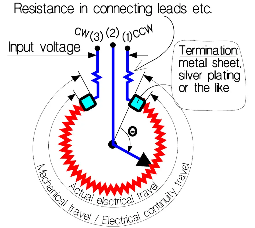
Between the two fixed terminals there is a third one connected to a sliding contact or Wiper. Because the direction of motion of the sliding contact is hidden in encapsulated types the fixed terminals usually are marked with
- CW, i.e., clockwise, and
- CCW, that stands for counterclockwise.
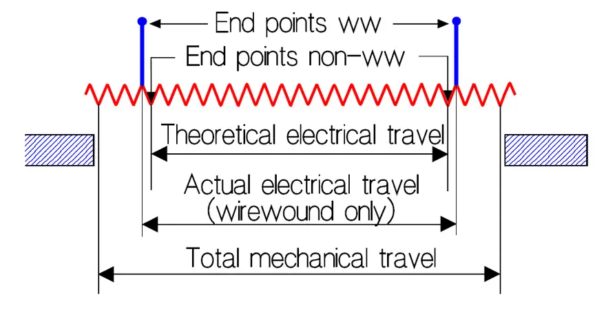
With the slider positioned in either of the two end points we measure between the fixed terminals the Rated resistance, Rtot, of the potentiometer. In Figure 1 we also have indicated the rest or End resistance, ER, that in wirewound potentiometers is measured between terminals (2) and (1) or (2) and (3) when the wiper is positioned in the corresponding end point where integral stops prevent further movement. In non-wirewounds the shaft shall be positioned at either of the theoretical end points, i.e., at the ends of the theoretical electrical travel (Figure 4). Sometimes the end resistance, ER, is expressed in % of Rtot. Precision wirewound potentiometers have terminations like the one in Figure 2.
If we measure the rest resistance we also get an extra contribution from the futile part of the resistance track (position B in the figure). If we move the wiper to position A the resistance will drop to a minimum, the so called Minimum resistance, MR. Instead of ER, for non-wirewound precision potentiometers the End voltage, EV, is specified.
According to industry standard of the Variable Resistive Components Institute (VRCI) measurement shall be done between the wiper and an end point. The shaft then is positioned at the theoretical end point (non-wirewound) or at the end point (wirewound). The theoretical end point is represented by position B1 in Figure 3., the end points of a wirewound potentiometer are represented by start of actual electrical travel in Figure 1. The end voltage is expressed in percent of the input voltage E.
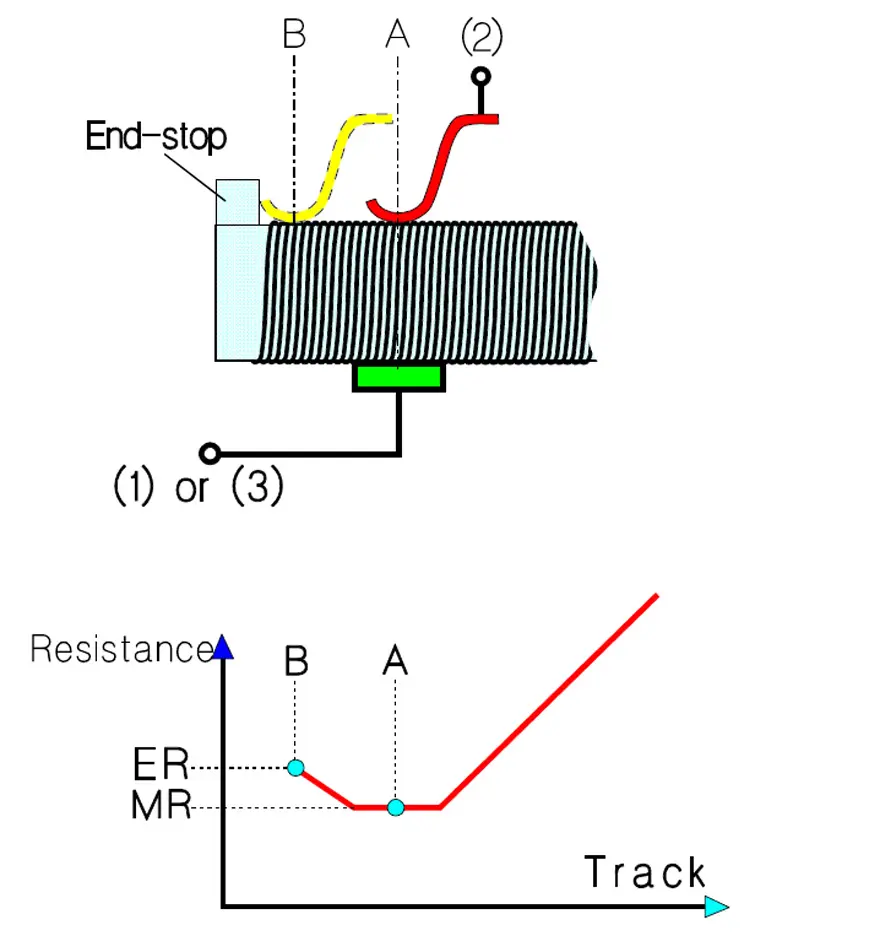
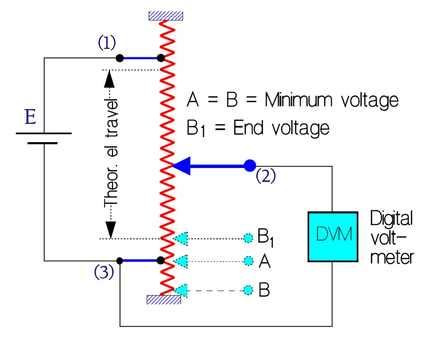
If we, as proposed, should measure in position B the result would be the same as in position A. The current through the DVM is assumed to be negligible.
The Minimum voltage MV is the smallest or lowest voltage between the wiper terminal and an end terminal when the shaft is positioned near the corresponding end of electrical continuity travel (Position A in Figure 3).
Actual electrical travel applies to wirewound potentiometers only and concerns the total travel between end points as shown in Figure 4.
In that point of the shaft travel where we start observing the first significant changes of the output voltage Type 2 potentiometers and trimmers sometimes have a definition of the Effective minimum resistance. Compared to the End Resistance, ER, it is approximately 10 times higher, for example 2% when the ER is specified to 0.2%.
The Total mechanical travel is determined by the total travel of the shaft between integral stops. If there are no stops (as in non-wirewound servo potentiometers) the mechanical travel is continuous and thus the mechanical travel 360°.
That part of the travel where we have a continuous electrical connection between wiper and terminals is called Electrical continuity travel. In wirewound potentiometers it coincides with the total mechanical travel.
At a specified shaft position the corresponding output ratio is defined as the Index point, IP. Usually IP is positioned at approximately 50% of the maximum output ratio. It is used to establish a shaft position reference, for example when specifying the Theoretical electrical travel that usually is centered between the end points of the actual electrical travel, Figure 4. Suppose now that the IP is defined at a shaft travel of 170°. The theoretical electrical travel then will range between 0 and 340°.
The Insulation resistance, IR, is measured with DC between the connected terminals and all other electrically conductive parts like shaft, metal housing, mounting details etc. IR should be at least 1000 MΩ.
Cycle. In potentiometer contexts we meet the expression cycle which means a shaft travel from one end point to the other and back to the starting point.
Rotational life. The specified maximum number of shaft revolutions that a potentiometer shall be able to stand with preserved resistance stability is called rotational life.
Potentiometer or Encoder – What is the difference?
A potentiometer and an encoder are both electromechanical devices used to measure position; however, the potentiometer outputs analog signals while the encoder outputs digital signals. Generally, the potentiometer has a shorter life and lower accuracy than the encoder but output more continuous analogue output.
Potentiometer or Rheostat
In principle a variable resistor may be used in two different ways with respect to the load: As a parallel resistor, i.e., as voltage divider or potentiometer, and as series resistor or rheostat, i.e., a type of current regulator.
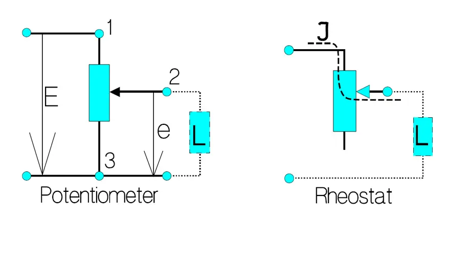
Figure 5. shows the principle functions of a potentiometer and a rheostat. The current through the rheostat may never exceed Imax in the formula
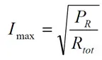
This formula applies also to the potentiometer.
Conformity
By means of the resistance track construction the output ratio may be made to follow non-linear functions like, for example, logarithmic, trigonometric etc. In order to specify the fidelity of the output ratio to such functions the concept conformity is used. It stands for permissible, practically determined output ratio deviations from a theoretical function. The conformity is expressed as a percentage of the total applied voltage.
Potentiometer Linearity
Introduction
The most common output ratio from a potentiometer is the straight one. Specification of the deviations from a straight reference line is a special case of conformity and has got its own name: linearity. Thus, it describes how well the output ratio follows the shaft travel. The linearity is expressed in percent of the total applied voltage. In the ideal case the output ratio should follow a straight line from 0 to 100% when the shaft is turned from one end point to the other. In practice, however, there are deviations or linearity errors and they may be defined in different ways. Following definition description will gain in clarity if we, for comparison reasons, place a copy of Figure 1. in close connection to Figure 7. The copy is called Figure 6.
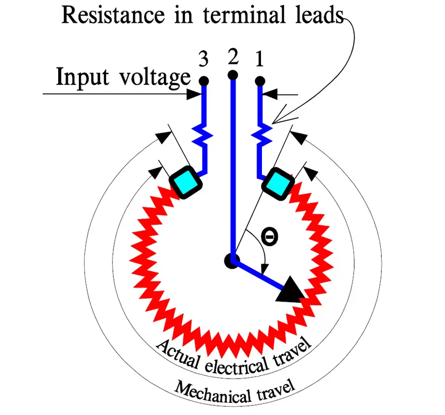
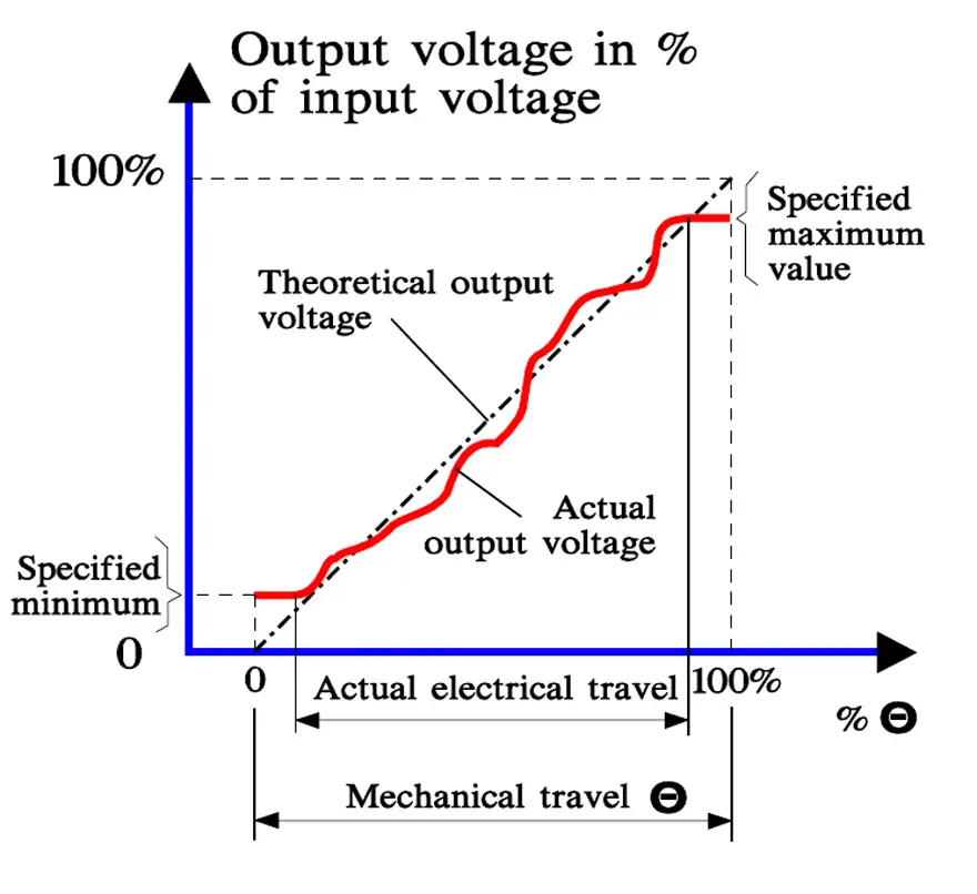
If we turn the potentiometer shaft (2) from one end point (1) to the other (3), the output voltage increases along a line that deviates more or less from the theoretical straight reference line. It may look like the curve in Figure 7.
If we compare Figure 6. with 7. we may imagine how the terminal metallization acts like a kind of landing-strip for the output voltage (the plane parts in the beginning and the end of the actual electrical travel).
Independent linearity
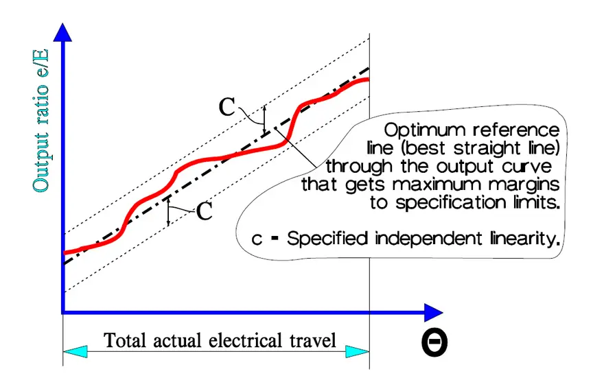
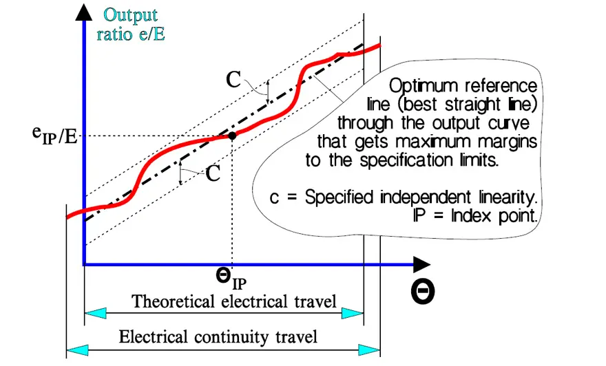
The least difficult way of defining linearity is by using Independent linearity. Here we restrict ourselves to either total actual electrical travel (wirewound) or to theoretical electrical travel (non-wirewound). An optimum center line is drawn through the output voltage curve together with two parallel specification limits. The margins between curve and limits then will be at maximum. The distances c in Figure 8. and 9. represent the specified independent linearity and are expressed in percent of the total applied voltage.
Specification of the independent linearity is used, for example, on such potentiometers where the user wants to adjust the gradient of the output voltage. It is done by means of built-in resistor elements connected to the potentiometer track.
Zero based linearity
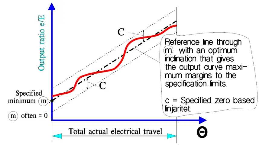
If we specify a minimum of the output ratio at the start of the actual electrical travel, draw a center line through this point and choose a slope that minimizes the maximum deviations, we obtain a reference line around which we may draw two parallel specification limits. They represent the zero based linearity and apply to wirewound potentiometers only. The specified minimum usually is zero, therefore the name (Figure 10). It is expressed in percent of the total applied voltage.
Terminal based linearity
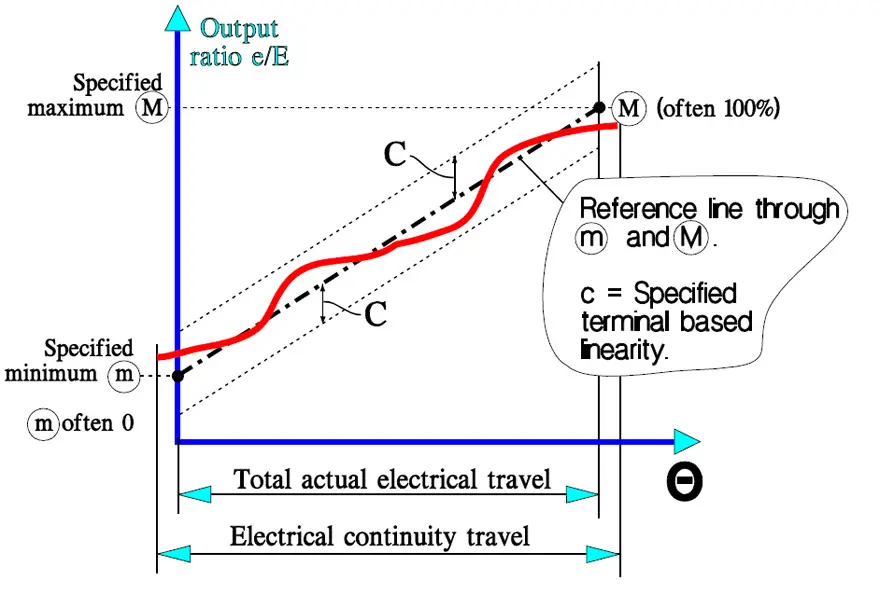
This linearity expresses the deviations from a center line through a specified minimum and maximum output ratios that are separated by the actual electrical travel. The specifications usually calls for 0 and 100% at minimum and maximum ratios. This linearity is also expressed in percent of the total applied voltage. It applies to wirewound styles only (Figure 11.).
Absolute linearity
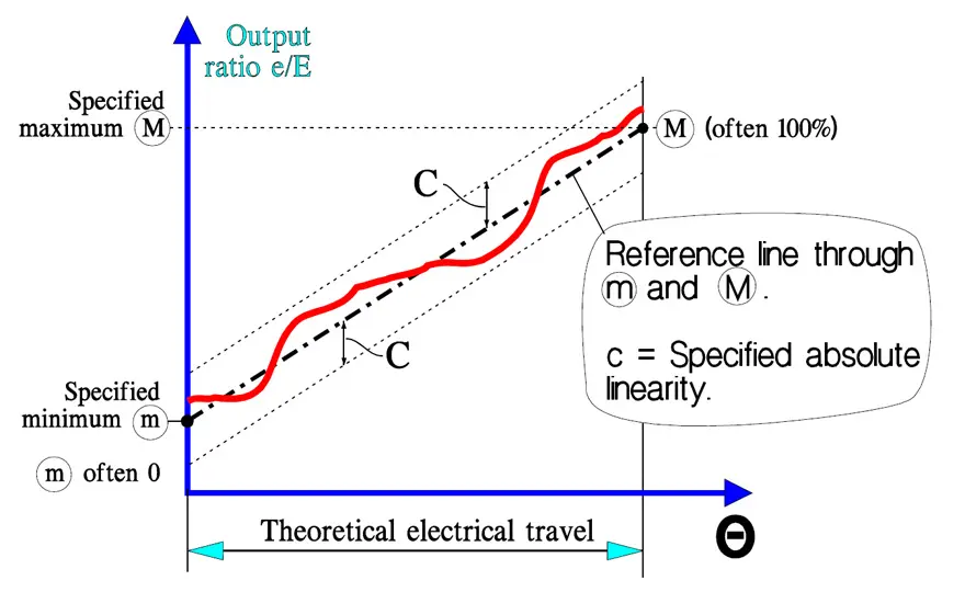
This linearity concept differs from the terminal based linearity only by the extension of output ratio records. They range over the theoretical electrical travel which means that an index point is required. Absolute linearity applies to both wirewound and non-wirewounds (Figure 12.).
Taps
Certain applications require additional terminals. These are called taps and exist in both wirewound and non-wirewound potentiometers. In the latter they have either of two functions: Current taps and voltage divider taps. The former ranges over the width of the whole resistance track and disrupt the linearity. The latter are located at the outermost edge of the track and don’t influence the linearity.
Gang potentiometers
Sometimes several potentiometer elements called cups are coupled together on a common shaft. The assembly is called a gang. The technique requires some definitions.
Phasing point
In order to meet the requirement of simultaneous conformity or tracking gang cups are phased together at a common reference position of the shaft. For linear potentiometers usually that shaft position is chosen where the output ratio e/E of the electrical elements is approximately 50%.
Tracking
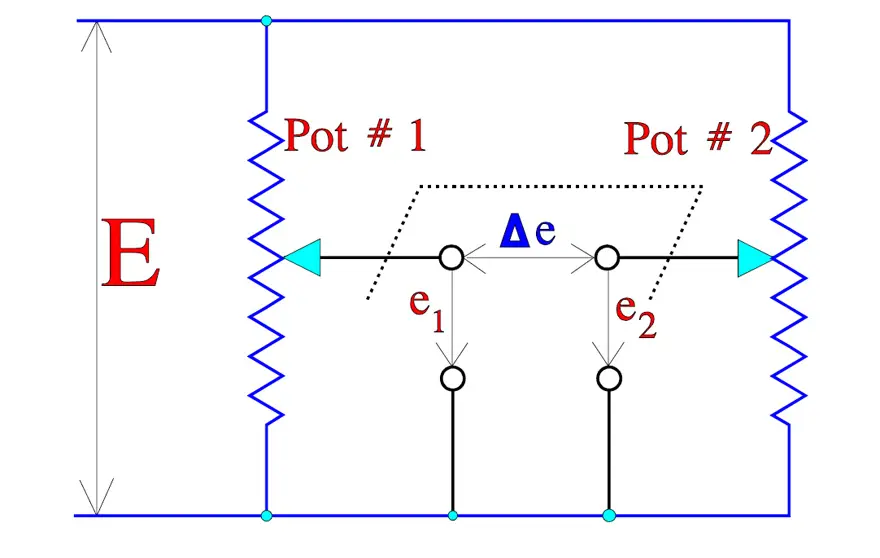
The mutual difference, at any shaft position, between the output ratios of the electrical elements of a gang is called tracking error. It is expressed in percent of the input voltage E. The first potentiometer section is taken as reference. In Figure 13. the tracking error of the two sections is Δe.
Simultaneous conformity
If we require that all the potentiometer elements in a gang simultaneously shall meet the requirements of conformity (or linearity) we talk of simultaneous conformity. The best result is achieved if the phasing point is localized at an output ratio of approximately 50%.
Loading Error
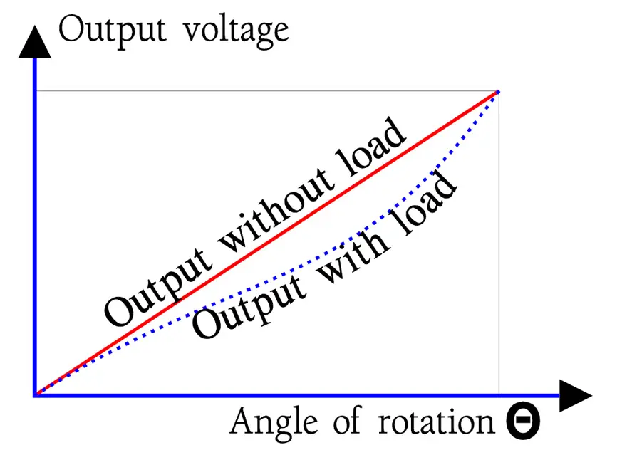
If we load a potentiometer as shown in Figure 14. the load will draw a certain current through the wiper. This will alter the proportionality of the voltage division slightly. The output curve will sag, with a maximum difference from the zero load line at approximately 2/3 of the maximum shaft rotation max. We get a linearity error or loading error. The error decreases with increasing load impedance.
Resolution
From MIL-R-39023 we quote the definition of resolution: ”A measure of the sensitivity to which the output ratio of the potentiometer may be set”. The same MIL standard also defines voltage resolution as “The maximum incremental change in output ratio with shaft travel in one direction in any specified portion of the resistance element” (applicable to wirewound only). The resolution is expressed in per cent of the input voltage E. The higher resolution the lower percentage.
Descriptions of non-wirewound potentiometers sometimes discuss “Infinite Resolution”. More literally it should be written “infinitely high resolution”. The resolution of a wirewound potentiometer with N number of turns may be approximated to the reciprocal 1/N.
Adjustability
The resolution of trim potentiometers has the name adjustability, which means setting accuracy or settability. It is stated in percent of the total applied voltage E (or of Rtot) and thus is a measure of the accuracy with which a desired voltage (or resistance) may be set.
Electrical performance by potentiometer technology
| Parameter | Wirewound / power pot | Cermet / conductive plastic / carbon |
|---|---|---|
| Typical TCR | Low; track is metallic, dominated by winding and ceramic body. | Medium to high; depends on film system, often dominated by composite or polymer matrix. |
| Linearity capability | Very good; multiple linearity definitions (independent, terminal‑based, absolute) available, especially in Type 1 precision designs. | Good to very good for cermet and conductive plastic; carbon composition parts usually show larger deviations and drift. |
| Contact resistance & noise | Very low CR and ENR; noise mainly affected by wiper current and oxide layers on the metal. | Higher CR; sliding noise and CRV more pronounced, mitigated by minimum wiper current and suitable track lubricants. |
| Resolution / adjustability | Discrete steps in wirewound; resolution ≈ 1 / number of turns for Type 1 multi‑turn devices. | Practically “infinite” resolution in non‑wirewound tracks; adjustability of trimmers limited by mechanical design and screw pitch. |
| Power capability | Medium to high; power potentiometers and rheostats are sized by power and current rating rather than only resistance value. | Low to medium; most cermet/carbon/conductive plastic types are signal‑level devices with limited continuous power dissipation. |
| Typical use | Power control, heater and lamp regulation, high‑current adjustment, precision servo feedback in Type 1. | Panel controls, calibration trimmers, precision single‑turn pots, front‑panel knobs in audio and instrumentation. |
Potentiometer noise
CRV Contact Resistance Variation
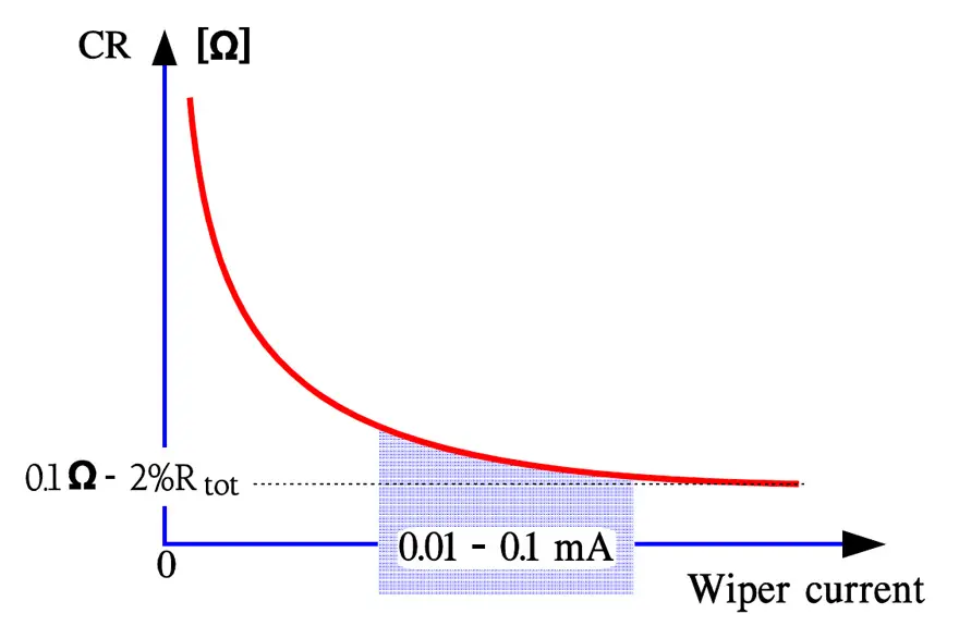
CRV stands for Contact Resistance Variation. Before we discuss this concept let us begin with Contact Resistance in general. The contact between wiper and track has a certain resistance the value of which depends on the contact pressure, the track material and its nature, the current through the wiper, etc. The Contact Resistance (CR) increases, for example, exponentially with decreasing wiper current somewhere below 1 to 0.1 mA. The more metal in the resistance element the less pronounced the phenomenon. Figure 15. shows in principle the CR of a cermet potentiometer but the curve could equally well be applied to a wirewound potentiometer.
In addition, the wiper current varies from point to point along the travel track. In addition to the contact resistance there is in non-wirewounds also a certain track material resistance (Figure 16.).
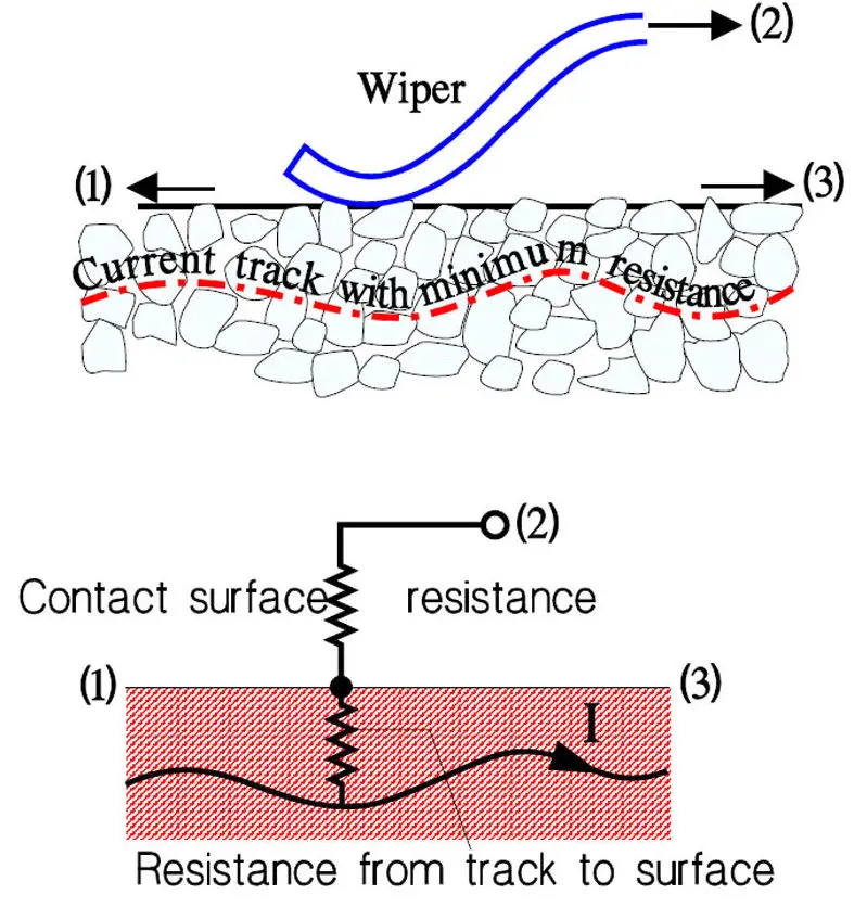
We can call the sum of all these static resistances Contact Resistance, CR. In the end points they are part of the end resistance ER respectively the minimum resistance MR. When the shaft then is moved over the track arbitrary resistance changes or dynamic Contact Resistance Variations, CRV, occur that in principle may look like the record shown in Figure 17.
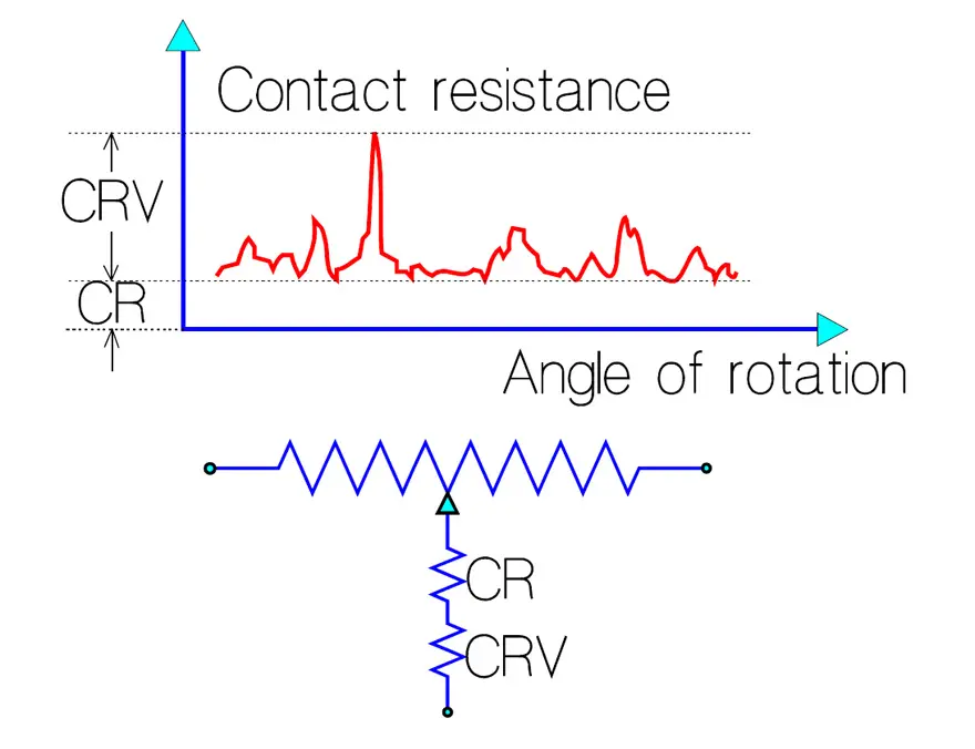
Usually CRV is specified for trim potentiometers and sometimes also for non-wirewound Type 2 potentiometers intended for panel mounting. A test circuit is used similar to the one in Figure R4-18 but with other data. A filter with a bandwidth of 100Hz – 50 kHz is needed. The current must also be adjusted to Rtot. CRV is expressed in percent of Rtot.
The figure applies in principle to both wirewound and non-wirewound potentiometers. Wirewounds have a fixed contact resistance (CR) that usually lies considerably below 1 ohm. Non-wirewound CRs are in the kohms range (See explanatory Figure 16.).
ENR Equivalent Noise Resistance
For wirewound potentiometers the Equivalent Noise Resistance, ENR, is specified. Usually it is measured according to the setup in Figure 18. The current generator feeds 1 mA through the wiper. The voltage drop across the contact then may be graded directly in ohms (1 mV corresponds to 1 ohm).
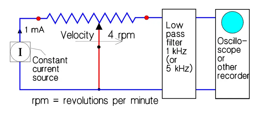
The measurement specifications – that are strongly influenced by the manufacturers, though based on a MIL specification – usually also prescribe that the shaft first shall be cycled 10 times over a minimum of 95% of the electrical continuity travel prior to noise measurements. That means that possible oxides and other debris that may occur on the track will be rather effectively worn off, thus giving a relatively insignificant measurements. Values below 0.1 ohm are not unusual. Furthermore the measurements shall be carried out at room temperature. If the application operates below zero the result from the ESR test is not relevant. Faster wiper movements than the specified 4 rpm also will yield a poorer noise result. At production inspection certainly higher velocities occur, as much as 100 rpm for certain designs. But sooner or later such velocities are obtained where the wiper starts bouncing over the turns.
In conclusion: For mutual comparisons between potentiometer types the above mentioned specification is good. ENR information from application conditions, however, may require additional measurements.
Output Smoothness
Output Smoothness means the maximum instantaneous variation of the output voltage compared to the ideal output. This parameter is applicable to non-wirewound precision potentiometers only. The high resistivity of the track material and the geometry of the wiper contribute to a considerably higher contact resistance (CR) than the one in wirewounds. There would be considerable power generated in the CR if we used the test equipment for ENR in Figure 18. Instead the test circuit in Figure 19. is used.
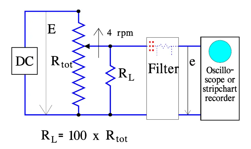
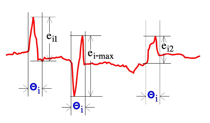
In order to avoid the output voltage gradient the filter blocks DC voltages. The filter time constant is chosen so that only sudden voltage changes during shaft movements shorter than 0.5° are recorded, i.e., ≤20 ms at 4 rpm. The output voltage “e” is measured over the theoretical electrical angle that is divided in intervals of 1%,Θi. If for, example, the theoretical angle is 300°, Θi will be 3°.The interval width is placed over occurring interesting voltage changes as shown in Figure 20. Output Smoothness is defined as the maximum output voltage change during one interval. Thus, in Figure 20 ei-max = the Output Smoothness of the record.
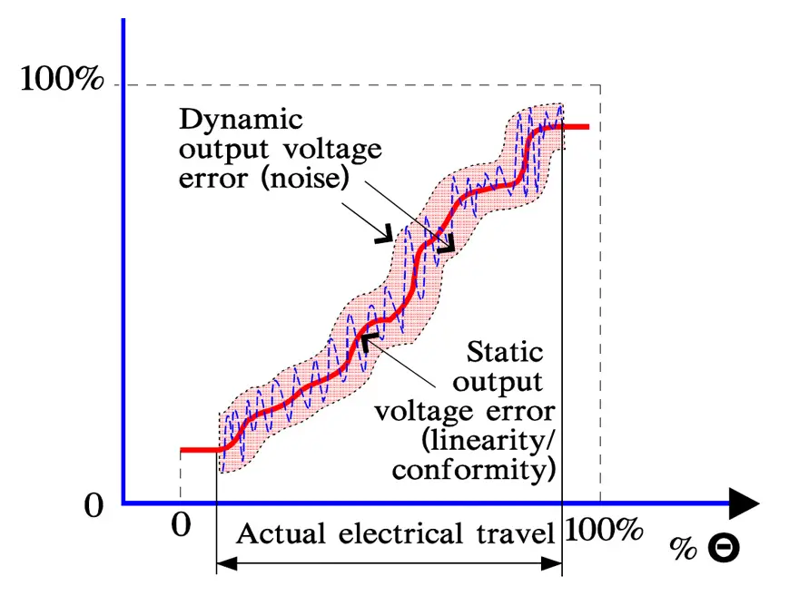
Summary about output voltage errors
The different types of output voltage errors that we have dealt with may be divided into static errors (deviations from the ideal output ratio) and dynamic ones (ENR, CRV and Output Smoothness). The latter are superimposed on the static ones as shown in following schematic.
Some mechanical definitions
The following formalized figures indicate the principle methods for determining mechanical properties. Different standards may state deviating forces and measures. US military specifications state, for example, ½ pound instead of 2 N and the distances are stated in inches (25.4 mm). The circle with a pointer symbol refers to a dial indicator for recording of mechanical movement. The figures are designed to be fully descriptive. Further detailed instructions have to be found in the standard in question.
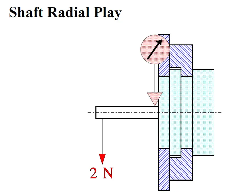
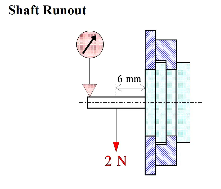
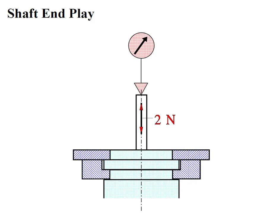
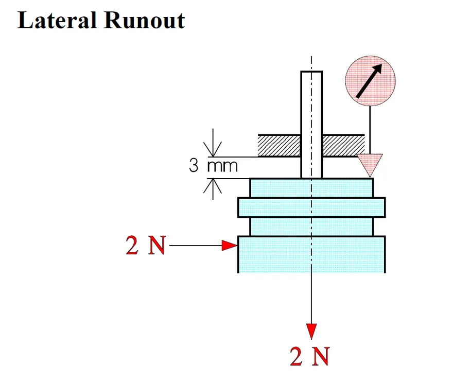
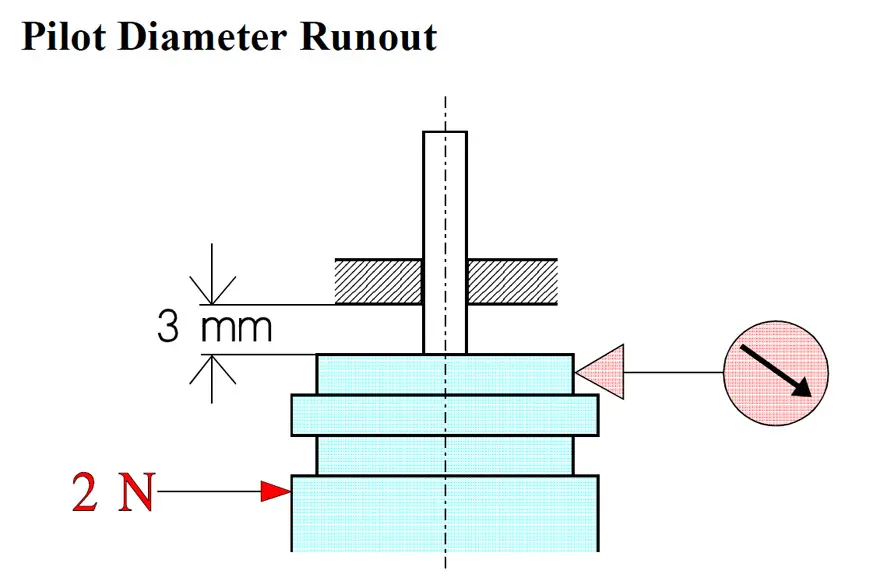
Figure 22.-26. Potentiometer mechanical configuration from left: Shaft End Play; Runout; End Play; Lateral Runout; Pilot Diameter Runout
Backlash
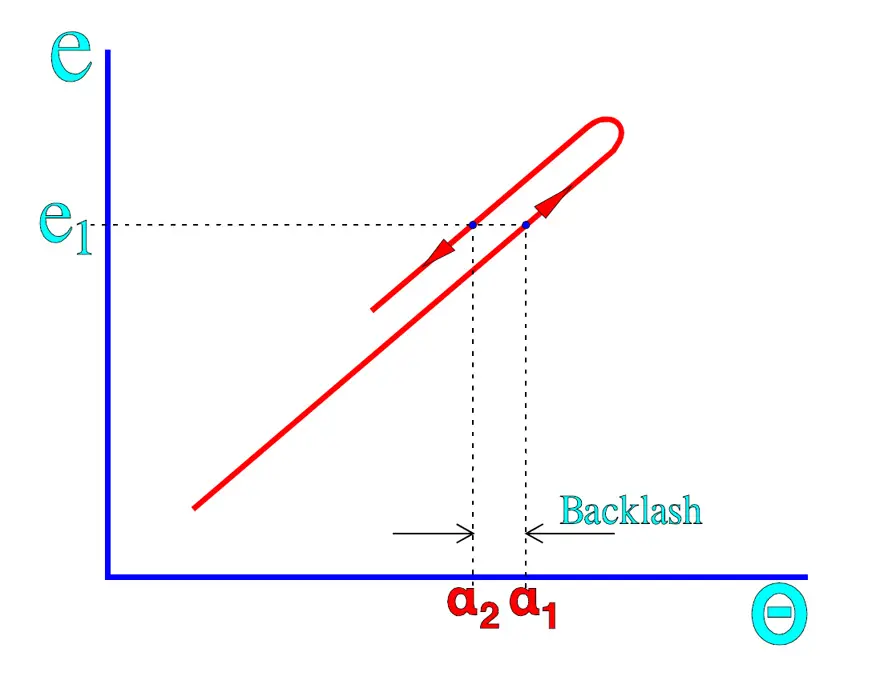
If we turn the shaft in one direction until the output voltage has attained a specified value that we call e1 at a travel angle Θ = α1 and continue the movement a little before we turn back, we have to pass α1 a certain way before we attain e = e1. This will happen at a travel angle Θ = α2 and depends on mechanical play in the wiper system. Backlash is defined as the maximum difference between α1 and α2 and thus is expressed in degrees. The case is illustrated in Figure 27. and describes a mechanical hysteresis.
Typical failure modes and mitigation
- Track wear and open segments: repeated mechanical cycling or overload can cause local burning or abrasion of the resistive element, leading to intermittent or open‑circuit behaviour near end turns or high‑stress regions.
- Increased contact noise: contamination, insufficient wiper current or oxide growth on metallic tracks increase CRV and ENR, which appears as audible or visible noise in analogue controls and feedback loops.
- Corrosion and chemical attack: sulfur‑containing atmospheres, aggressive cleaning fluids or flux residues can attack silver contacts, cermet films or copper terminations, eventually causing high contact resistance or leakage paths.
- Lubricant migration and “silicone infection”: certain greases creep out of the potentiometer cavity, contaminating nearby contacts, optical elements or bonding surfaces and degrading system performance.
- Mechanical damage: excessive shaft torque, shock, vibration or poor panel mounting can introduce play, backlash or fracture of the wiper system, resulting in mechanical hysteresis and unstable settings.
Mitigation measures include conservative power and wiper‑current derating, selecting sealed or hermetic styles for polluted or humid environments, staking critical trimmer settings, choosing suitable lubricants and migrating to non‑contact sensor solutions for very high cycling or safety‑relevant applications.
Potentiometer Type 2
Power potentiometers

Power potentiometers are as a rule wirewound. They are wound on a ceramic body and lack, due to heat dissipation concerns, encapsulation in casings or housings. Often they have a touch protection of silicone lacquer, cement or enamel and they are readily used as rheostats. If we turn the shaft of a rheostat towards zero resistance it is not unusual that the current burns off the last turns in the winding if the load impedance is low. Hence, the current in a rheostat must not exceed that of the rated power.
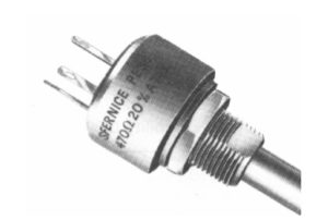
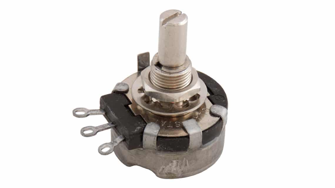
The sliding contact of the wiper sometimes consists of silver. If there are sulfur compounds in the air, for example from oil incineration plants, silver sulfides are formed on the sliding contact. If they are not worn off by frequently recurrent adjustments, the next change of position will cause ESR values going towards open circuit modes. A typical example of a power potentiometer is shown in Figure 28.
Panel mount potentiometers Type 2
Under this heading are collected wirewounds with bobbins of fiber card or the like and non-wirewounds with resistance elements of molded carbon composition, conductive plastic or cermet applied on substrates of laminated paper (bakelite paper), plastic or ceramics. In order to prevent the potentiometer housing from separating when the shaft is turned, the housing or mounting plate is supplied with an anti-rotation pin that fits in a corresponding hole in the panel.
The most simple carbon potentiometers have a sprayed and dried carbon compound on bakelite paper. After a number of cycles they will meet with contact disturbance (noise) due to wear grooves in the track and wear debris around the wiper. The best rotational life is with the conductive plastic potentiometer. Due to the metal particles in the cermet it develops an abrasive action that wears on the wiper. Therefore the track is often lubricated with a grease of some kind which reduces the wear.
Usually the potentiometers are encapsulated, for more severe environments “hermetically”, which here means seal rings around the shaft. A smaller degree of sealing is offered by the so called “dust-proof” ones. Surface Mount potentiometers exist, both with and without encapsulation. If the assembly process involves washing, the design at least must be tight against rinsing fluids. Otherwise rinsing products like flux residues may be deposited on the track which can lead to severe contact disturbances.
A phenomenon that threatens components with cavities, if they are subjected to temperature changes in humid environments, is the so called pumping effect. An insufficiently sealed potentiometer with large cavities inside the housing is particularly subject to this phenomenon. If humid air in the cavities is cooled the water vapor will condense and create a negative pressure in the cavity at the next temperature rise.
New humid air is sucked in, etc. Instead of having such a half-tight potentiometer, a hole in the bottom of it would be better, so that condensed water could run out…Thus, use qualitatively sealed potentiometers if the environment requires. Especially those with a carbon track, conductive plastic or wire winding are sensitive to moisture. A special type of carbon track potentiometer is the slider pot with a linear motion. It is usually used in audio controls in studio mixer panels.
It is important that the bulk track is molded and thus relatively wear resistant, partly to allow long use, and, partly so that noise producing wear will be prevented. Caution! If one has chosen some type of slider potentiometer it is usually difficult to find any equivalent second source.
Current derating
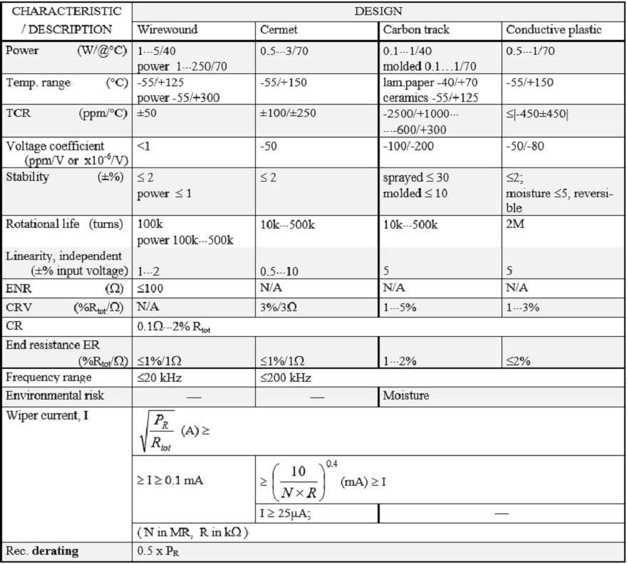
The current through the wiper should in potentiometers with a carbon or conductive plastic track be kept low in order to minimize noise and wear, preferably values less than 0.25 mA. Wirewound potentiometers, on the other hand, should draw a certain minimum current through the wiper – more than 0.1 mA – in order to reduce noise and contact disturbances. The contact resistance in cermet potentiometers has the sensitivity of the metals to small currents and should likewise carry a certain minimum current. An adequate minimum value might be 25 µA. The data sheets also state a certain maximum current through the wiper, for example, 100 mA at resistances below 100 ohms. At higher resistance values the contact resistance CR increases, which could lead to local overheating if the wiper current is not kept down.
Thus, the wiper current is determined not only by the resistance value but also by nominal power, resistance track material and rotational life (number of shaft turns). In the summary tables we shall describe some guiding formulas for the wiper current I that is confined within certain limits. The highest limit is the maximum power current of the potentiometer, that may be calculated from the equation.

Next maximum limit – that never must be greater than the maximum power current – is calculated by means of a formula that contains the rotational life N expressed in number of million shaft revolutions (megarevolutions, “MR”) and the resistance in question expressed in kohms. The result is obtained in mA.

Finally there exists a commonly recommended minimum limit. Example. Suppose a cermet potentiometer with PR = 0.5 W, N = 100 000 revolutions = 0.1 MR, R = 1 MΩ = 1000 kΩ and the minimum limit for cermet = 25 µA. If we insert 0.1 and 1000 respectively in the applicable formula

we obtain
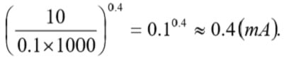
This value is well below the absolute maximum current derived from 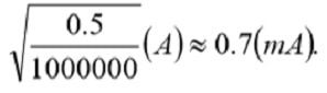
Thus the wiper current should be adjusted to lie between 0.4 mA and 25 µA.

Precision Potentiometers Type 1
According to IEC precision potentiometers are classified as Type 1. They exist in both bushing mount styles and in servo applications. In the latter case high demands are made for rotational life and low torque. Such potentiometers are supplied with ball bearings. If they in addition are sealed against moisture this will influence the torque. The solution of such problems implies explicit requirement specifications and close cooperation with prospective manufacturers. For very severe environments there exist, among other things, oil-filled potentiometers.
Wirewound, Type 1
Wiper current Resistance elements formed from metal always form oxides on the surface that the wiper has to break through in order to establish electrical contact. The break through may be carried out by movement wear and by means of electrical voltage. If the potentiometer operates at dry circuit conditions, i.e., 10⋅⋅⋅30 mV and wiper currents less than 10 µA, this will make the contact more difficult and increase the noise disturbance. The schematic for a cermet potentiometer in Figure 15. also is applicable to wirewounds.
The disturbances also increase at decreasing temperatures and seem to be still more pronounced when the temperature is below –30 °C. Thus, the wiper requires a certain current in order to get a noise free operation, preferably more than 0.1 mA. Lubricants In order to reduce the wear and prevent oxidation, both on track and wiper, the track is in most cases lubricated with some kind of grease or oil. Most common are silicone compounds where the viscosity is relatively constant over a broad temperature range. The silicones, however, show a rapidly increasing viscosity when greases reach temperatures below –5⋅⋅⋅ -15 °C and oils below –30⋅⋅⋅ -40 °C. In addition at a moderate wiper speed the wiper tends to slide on top of the lubricant film, causing the ENR values to rise unacceptably. Silicone lubricants have a characteristic that in certain applications may be disastrous to the surroundings: they “creep”.
Their surface tension is so low that the lubricant “wets” adjacent surfaces that are contaminated with a thin film. We talk about a silicone infection. A small dab of grease will within months spread over square meter large areas. The phenomenon causes problems in following ways:
- Contaminated surfaces might be electrically isolated by the lubricant film at dry circuit conditions.
- Contaminated contacts with a breaking function accompanied by arc overs, will be isolated by the silicone granules that are formed when the miniature arcs decompose the silicone film.
- Contaminated lens systems in high energy lasers will have their lens surface damaged by the laser beam when it burns the silicone film.
- Gluing of components on contaminated surfaces is made impossible.
Single-Turn
Figure 30. depicts a typical single-turn servo potentiometer. There are precision styles for bushing mount applications and there exist two designs: with and without end-stops. The latter is called continuous which means, an electrical discontinuity occurs when the wiper traverse the non-conductive gap located between the ends of electrical continuity travel. The resistance wire sometimes consists of gold-platinum alloys. They are used where the contact pressure of the wiper has to be low and oxide formations minimized, for example in gyro potentiometers.
Multi-Turn
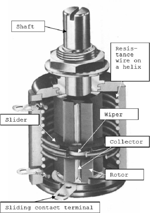
If we, on a thick isolation lacquered copper wire wind a resistance wire, and bend this “wire bobbin” into a helix we obtain a resistance element for a multi-turn potentiometer, as shown in Figure 31. This helical element then is fitted in a housing and connected to terminals. The shaft is supplied with a sleeve with a longitudinal spline and an electrical contact track.
On this rotor a slider then travels that makes contact both with the track and the resistance helix. The slider also is supplied with cams that trace against the inner side of the housing and move the slider along the rotor when shaft is turned. The common number of turns is 3, 5 or 10 but higher numbers exist. The electrical angle is usually defined in multiples of the number of turns. Thus, a 10 turn has the angle 3600°. That means, among other things, that the resolution becomes better and the setting accuracy greater.
Hybrid Potentiometers
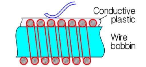
If the resistance wire of a multi-turn potentiometer is coated with conductive plastic as shown in Figure 32. we have a combination element of wire and plastic, a so called hybrid, that makes possible a multi-turn construction with conductive plastic. There are certain benefits with the smooth conductive plastic surface and the current capability of the embedded wire but the construction is, of course, more expensive than that of a conventional multiturn wirewound potentiometer.
Lubricants on the hybrid track are necessary. Otherwise the track will be worn down after a small fraction of the specified rotational life. The principle for multi-turn constructions might be applied on conductive plastic (CP) if the lacquer isolated copper wire bobbin is directly coated with CP. Use of this process, however, is quite exceptional.
Non-wirewounds, Type 1
Normally non-wirewound precision potentiometers are manufactured as single-turn devices. Except for conductive plastic cermet is used, as well bushing mount styles, in servo applications. The design from Figure 30. could as well be applicable to a nonwirewound servo potentiometer. Just as in servo applications the rotational life has to be high and puts high demands on the wiper design, the contact pressure and the track which therefore has to be polished. The polished CP track allows a number of revolutions of several tens of millions.
Then, however, the wiper current must be limited. Otherwise a kind of welding effects on the contact surfaces along the track results, that will destroy both wiper and surface and increase wear and noise. The wiper current should be limited to maximum of 0.25 mA. Example: A serious manufacturer promised a rotational life of 100 x 106 revolutions at 2 mA. But he recommended a maximum wiper current of 10 µA! The 0.25 mA rule, however, is not unconditional. Material, resistance value, nominal power and the number of revolutions of the rotational life come into play. The wiper current in wirewound and cermet potentiometers should comply with Formula 2.

The contact function of cermet potentiometers is in its nature suggestive of that of the metals. Therefore the wiper current should, just as in wirewounds, also be limited in low values. An approximate minimum value might be 25 µA. (Figure 15). In the summary tables some guiding formulas are stated.
Linear motion potentiometers
A parallel to the slider potentiometer but in Type 1 design are the linear actuated precision potentiometers or linear position transducers. Thus, they have a straight resistance track and a piston or guide bar that holds the wiper and transforms linear motions. The mechanical travels vary between 10 mm and 1.2 m. The resistance tracks are made of wirewound or hybrid elements, of cermet or conductive plastic. As to other parameters they have the same characteristics and specifications that apply to corresponding rotary potentiometers.

Trimmers
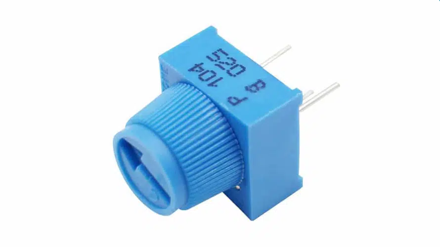
The need for small, adjustable resistors created trim potentiometers. They lack the potentiometer shaft and are operated through an adjustment screw or a rotor. The setting needs to be maintained during handling and environmental influence. Thus, the contact pressure of the wiper is high. The setting stability is specified as a voltage change expressed in percent of input voltage. The first trimming potentiometers had a carbon track or a wirewound element.
The carbon track potentiometers exist in a variety of designs, both for surface mount and hole mount, from the cheapest and most simple designs with a substrate of bakelite paper or the like and a sprayed suspension to conductive plastic on a ceramic substrate. The most predominant material, however, is cermet, not least due to the breaking into the market of SMD designs.
Wirewounds still exist due to their better tolerances and lower TCR. But this design suffers sensitivity to a basic mechanical problem. On one hand the wire has to be thin in order to achieve high resistance values, on the other the contact pressure from the wiper needs to be high in order to give a stable setting and a low noise. After a few trim operations the wire might be pulled in two. Moreover the corrosion risk is high if moisture gets inside the housing of the trimmer. With the better and better characteristics that characterize the cermet trimmers of today the need for wirewounds has strongly decreased. If we need better characteristics we preferably should use metal foil trimmers, in spite of their higher price. Just as conventional potentiometers, trim potentiometers are also encapsulated with O ring seals for more severe environments.
SM trimmers that will be subjected to washing fluids should at least have a design that is tight enough to withstand the rinsing process. Otherwise rinsing products like flux residues may deposit on the track which can cause severe contact disturbances. Hole mount types may entice someone into bending the leads. Then it is important that the lead inlets in the potentiometer housing are relieved. Otherwise forces easily are transferred to the joints with the resistance track and its substrate. In consequence either the substrate or the solder joint cracks, thus resulting in an open-circuit.
Talking of cracks, the long multi-turn rectangular 1¼” trimmers of the same basic design as the one in Figure R636 are more sensitive to exterior mechanical forces than the shorter ¾” design. Of course, the latter also has to be handled with care. The ¾” size fortunately has more and more replaced the 1¼” style and is itself being replaced by the more common 3/8” or ½” square styles. The square types exist in single-turn designs as well as ¼” and 4 mm diameter potentiometers. SMDs exist as single-turn styles in sizes of 3 or 4 mm square, the latter also in a multi-turn design. Just as hole mount potentiometers the trimmers are marked with movement direction (Figure 34.).
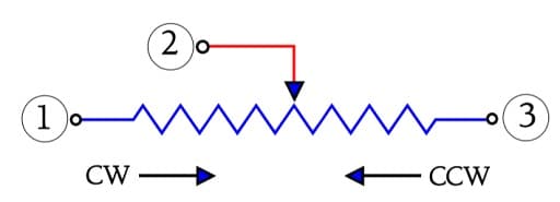
Trimming potentiometers shall, after trimming, maintain their setting without any alterations. Thus, as said before the contact pressure is high. This means, however, that the rotational life suffers by reduction. The number of cycles – wiper travel backwards and forwards along the track – seldom are specified for more than 200 cycles; for general purpose trimmers even less. Staking in high reliability applications is often used to maintain settings once a circuit is trimmed.
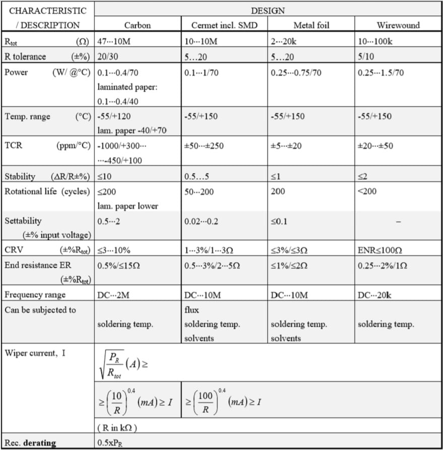
The wiper current must not exceed certain specified maximum values that for wirewound and cermet potentiometers may range as high as to 100 mA. Furthermore, for minimizing the noise the wiper current should be kept above certain minimum values. Both the maximum and minimum values are determined by rated resistance and track material. The following formulas may serve as a guidance at the same time as they contain certain derating information. If the resistance value in question is called R and is expressed in kΩ when we insert it in the “0.4 power fraction” we get the following conditions.
Cermet and wirewound:
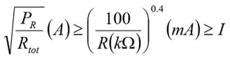
Example. R=100 Ω gives I=[100/0.1]0.4 ≈ 16 mA
Carbon track and conductive plastic:
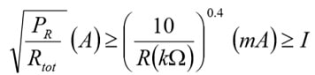
Example. R=100kΩ gives I=[10/100]0.4 ≈ 0.4mA.
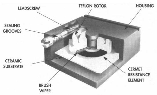
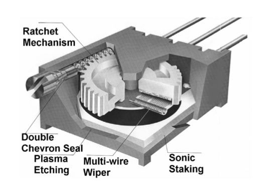
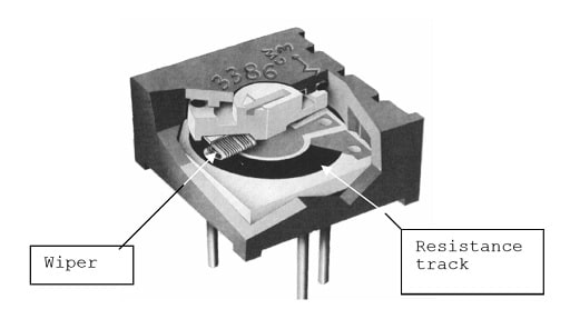
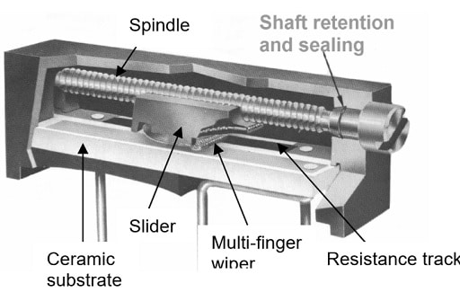
As already mentioned the trimming potentiometer designs and sizes vary significantly. Round, cheap single turn carbon or cermet track trimmers exist, with a varying degree of sealing, both for SM or hole mount applications. Multi- turn trimmers in round, square and rectangular housings exist, with a varying degree of sealing and wear resistance. Because there are no multi-turn tracks a mechanical gear change is used. By means of an adjustment screw and a worm gear and a circular track or a geared spindle drive – a kind of screw where the “nut” serves as holding fixture for the wiper – and a long straight track the multi-turn function is accomplished. Figure 35. -38. show some cutaway views from the manufacturers BI technologies and Bourns.
Conclusion
Variable resistors in the form of potentiometers, rheostats and trimmers remain essential building blocks for user controls, calibration functions, power regulation and position sensing, despite competition from digital potentiometers and non‑contact sensor technologies.
Understanding resistance and travel concepts, linearity and conformity definitions, contact‑noise mechanisms and mechanical parameters such as play and backlash allows designers to select and apply these components with confidence in both analogue and mixed‑signal systems. As environmental and functional‑safety demands increase, careful attention to wiper‑current limits, power derating, sealing quality and the choice between mechanical and solid‑state solutions becomes critical to long‑term reliability.
This overview, together with the selection guidelines and technology comparison tables, is intended as a practical reference for engineers working with passive components, power converters and position‑sensor applications.
FAQ: Potentiometers, Rheostats, Trimmers and other Variable Resistors
A variable resistor is an electromechanical component whose resistance value can be adjusted by mechanical motion, typically used for voltage division, current regulation or calibration.
A potentiometer is normally wired as a three‑terminal voltage divider with an adjustable output voltage, while a rheostat is used as a two‑terminal series resistor to control current; the same mechanical part can often be wired in either configuration, but rheostat applications usually require higher power and current ratings.
A potentiometer provides a continuous analog output proportional to shaft position, whereas an encoder outputs digital position information with higher accuracy and longer life.
Variable resistors have mechanical contacts and moving parts that introduce wear, noise and additional failure modes compared to fixed resistors.
Trimmers are “set‑and‑forget” variable resistors intended for infrequent adjustment, typically during factory calibration or service, whereas panel‑mount potentiometers are designed for repeated user operation and easier accessibility; using a trimmer for frequently adjusted controls will accelerate wear and increase contact noise.
The basic types cover Type 2 power and panel‑mount potentiometers, Type 1 precision potentiometers (single‑turn, multi‑turn, linear) and a wide range of trimmers.
Key error sources include linearity and conformity deviations, loading error, contact resistance variation (CRV), equivalent noise resistance (ENR) and output smoothness issues.
Reduce contact‑resistance variations by operating within recommended wiper‑current ranges, avoid overload and hot spots on the track, choose suitable track and wiper materials, and use sealed or hermetic styles in contaminated or humid environments; in very high‑cycling or safety‑critical functions consider non‑contact sensor alternatives.
Wiper current must be kept within recommended limits to avoid excessive noise, local overheating and premature wear, with different ranges for wirewound, cermet, carbon and conductive plastic tracks.
Non‑contact technologies such as Hall‑effect, magnetoresistive, inductive or optical encoders are preferred when cycling is very high, environments are dusty or corrosive, safety requirements are stringent, or when direct digital interfaces are required; mechanical potentiometers remain attractive in simpler analogue controls and moderate‑lifetime feedback functions.
Digital potentiometers are limited by their IC supply rails, internal structure and maximum wiper current, so they are not drop‑in replacements in high‑power or high‑voltage circuits; they are best used in low‑level feedback or calibration networks under microcontroller control, with proper attention to ESD and EMC.
Panel‑mount and power potentiometers can reach from 10⁴ to 10⁶ rotational cycles depending on technology and load, while trimmers are typically specified for tens to hundreds of meaningful adjustments and rely more on setting stability than frequent operation.
How to select a suitable potentiometer, rheostat or trimmer
- Step 1 – Define the electrical function
Decide whether the device will operate as a three‑terminal voltage divider (potentiometer), a two‑terminal series element for current or power control (rheostat), or an infrequently adjusted calibration element (trimmer).
- Step 2 – Specify resistance, power and wiper current
Determine required total resistance and calculate power dissipation and wiper current in the intended circuit; ensure both remain within the specified limits for the chosen technology over the full range of adjustment and expected duty cycle.
- Step 3 – Choose the technology and construction
Select between wirewound, cermet, carbon or conductive‑plastic tracks and decide on Type 2 power/panel‑mount devices, Type 1 precision potentiometers, or trimmers; base the choice on accuracy, linearity, contact‑noise behaviour, lifetime, and cost.
- Step 4 – Consider linearity and error performance
Check specified linearity or conformity, resolution and loading error, especially for precision applications where deviations from the ideal transfer function must be tightly controlled.
- Step 5 – Check mechanical and environmental constraints
Define shaft type, mounting style, sealing level, operating temperature, vibration and shock requirements, and verify that the chosen part meets relevant standards such as IEC/EN 60393 for potentiometers and AEC‑Q100 for IC‑based digital or non‑contact solutions.
- Step 6 – Evaluate reliability and adjustment strategy
Consider rotational or adjustment life ratings, setting stability, and whether controls will be user‑operated or factory‑set; plan calibration, staking or locking methods for critical trimmers and evaluate non‑contact position sensors where very high cycling or safety‑critical functions are involved.
- Step 7 – Decide if an alternative technology is better
For very high cycling, remote or automated adjustment, or harsh environments, evaluate digital potentiometers, Hall‑effect or magnetoresistive sensors or encoders as potential alternatives to classical mechanical variable resistors.
- Verify compatibility with the rest of the system
For digital potentiometers and sensor‑based replacements, check interface requirements (analogue, PWM, SPI, I²C), supply voltages, EMC and functional‑safety constraints, and ensure the chosen solution integrates cleanly with microcontrollers, ADCs or motor‑control ICs.
References and further reading
- IEC/EN 60393 – Potentiometers for use in electronic equipment
- Potentiometer, Preset Potentiometers and Rheostats – Electronics Tutorials
- All You Need to Know About Potentiometers – SameSky Devices
- Smart non‑contact potentiometers for industrial and automotive applications – Asemi
- Potentiometers, Encoder, Rheostats and Trimmers – Passive Components Blog
- Position Sensors – example overview of potentiometric vs other sensor types