Passive Components Blog
No Result
View All Result
  • Home
  • NewsFilter
    • All
    • Aerospace & Defence
    • Antenna
    • Applications
    • Automotive
    • Capacitors
    • Circuit Protection Devices
    • electro-mechanical news
    • Filters
    • Fuses
    • Inductors
    • Industrial
    • Integrated Passives
    • inter-connect news
    • Market & Supply Chain
    • Market Insights
    • Medical
    • Modelling and Simulation
    • New Materials & Supply
    • New Technologies
    • Non-linear Passives
    • Oscillators
    • Passive Sensors News
    • Resistors
    • RF & Microwave
    • Telecommunication
    • Weekly Digest

    Bourns Releases Automotive 1W Flyback Transformer

    Wk 20 Electronics Supply Chain Digest

    Inductor Resonances and its Impact to EMI

    Developing Low Inductance Film Capacitor using Bode 100 Analyzer

    Highly Reliable Flex Rigid PCBs, Würth Elektronik Webinar

    Würth Elektronik Releases High Performance TLVR Coupled Inductors

    YAGEO Extends Rectangular Aluminum Electrolytic Capacitor Family

    Dr. Tomas Zednicek Vision for Europe 2025 Passive Electronics Market

    Littelfuse Releases Industry-First SMD Fuse with 1500A Interrupting Rating at 277V

    Trending Tags

    • Ripple Current
    • RF
    • Leakage Current
    • Tantalum vs Ceramic
    • Snubber
    • Low ESR
    • Feedthrough
    • Derating
    • Dielectric Constant
    • New Products
    • Market Reports
  • VideoFilter
    • All
    • Antenna videos
    • Capacitor videos
    • Circuit Protection Video
    • Filter videos
    • Fuse videos
    • Inductor videos
    • Inter-Connect Video
    • Non-linear passives videos
    • Oscillator videos
    • Passive sensors videos
    • Resistor videos

    Inductor Resonances and its Impact to EMI

    Highly Reliable Flex Rigid PCBs, Würth Elektronik Webinar

    Causes of Oscillations in Flyback Converters

    How to design a 60W Flyback Transformer

    Modeling and Simulation of Leakage Inductance

    Power Inductor Considerations for AI High Power Computing – Vishay Video

    Coupled Inductors in Multiphase Boost Converters

    VPG Demonstrates Precision Resistor in Cryogenic Conditions

    Comparison Testing of Chip Resistor Technologies Under High Vibration

    Trending Tags

    • Capacitors explained
    • Inductors explained
    • Resistors explained
    • Filters explained
    • Application Video Guidelines
    • EMC
    • New Products
    • Ripple Current
    • Simulation
    • Tantalum vs Ceramic
  • Knowledge Blog
  • Suppliers
    • Who is Who
  • Events
No Result
View All Result
Passive Components Blog
No Result
View All Result

Skin and Proximity Losses as Key Impact Factors of Transformer and Inductor Winding Losses

2.5.2025
Reading Time: 6 mins read
A A

Pablo Blázquez, Power Εlectronics Εngineer of Frenetic in this blog explains main transformers and inductors winding losses key contributors: Skin and Proximity losses.

Transformers and Inductors get warm when they’re in use? Well, part of the reason lies in what we call Winding Losses. 

RelatedPosts

Inductor Resonances and its Impact to EMI

How to design a 60W Flyback Transformer

Rogowski Coil Current Sensor Explained

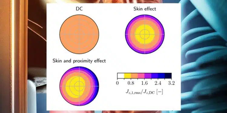
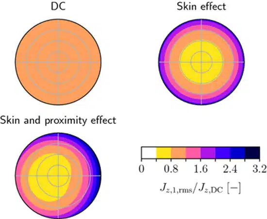
My focus for today is to explain what I´ve learned about the specific effects that lead to these losses and temperature rise, with a particular focus on two key players: skin and proximity losses – see Figure 1.

By understanding how they impact the efficiency and performance of our magnetic components, we will know how to combat these effects.

Skin Losses

Skin losses, also known as skin effect losses, are an important aspect of winding losses in Transformers and Inductors. When the alternating current flows through the wire, it tends to concentrate more on the outer surface due to the skin effect. This results in an underutilization of the inner part of the wire, that leads to energy losses. The current prefers the outer layers of the wire, leaving the inner layers unused.

Minimizing skin losses is crucial for the optimization of these devices’ efficiency. We can reduce wasteful energy dissipation by ensuring a more even distribution of current across the wire.

Figure 1. Skin and Proximity effect to winding losses

When it comes to combating this effect, different winding designs come into play. One popular solution is the use of Litz wire, which is composed of multiple individually insulated strands woven together. This configuration helps to distribute the current more evenly across the wire, therefore reducing the skin effect and minimizing energy losses. It’s like giving each strand of spaghetti a fair share of the delicious sauce!

Proximity Losses

Proximity losses are another significant component of winding losses in Transformers and Inductors that deserves our attention. When multiple windings are in close proximity to each other, their magnetic fields interact, and this results in energy losses. It’s like neighboring windings interfering with each other’s magnetic moves, causing inefficiencies. To minimize these losses, proper insulation between the windings is crucial. By implementing insulation techniques, we can reduce the magnetic coupling between the windings, mitigating proximity losses.

Think of it as creating a barrier between dancers at a party, preventing their magnetic interactions from causing excessive energy dissipation. Understanding and addressing proximity losses is key to enhancing the efficiency and performance of our winding designs.

Wire Types Winding Losses Impact

Different types of wire configurations have varying impacts on both skin and proximity losses in Transformers and Inductors.

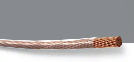
Litz Wire

As said before, it is composed of individually insulated strands woven together, which significantly reduces skin losses. Distributing the current more evenly across the wire mitigates the concentration of current on the outer surface, thereby minimizing energy dissipation. Additionally, proper insulation between the strands helps to reduce proximity losses by limiting magnetic coupling between adjacent windings.

Figure 2. Litz wire

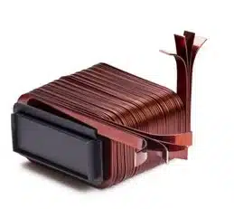
Rectangular Wires

They offer a favorable shape for reducing skin losses. The wider surface area allows for better current distribution, minimizing the concentration of current on the outer surface and reducing energy dissipation. Proximity losses can also be mitigated with careful positioning and insulation.

Figure 4. Rectangular wire inductor

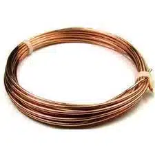
Round Wires

Although common and easy to work with, round wires tend to have higher skin losses compared to other shapes. The circular cross-section results in a larger surface area, leading to more concentrated current flow on the outer surface and increased energy losses. Proximity losses can also be influenced by round wires, as their close positioning may result in stronger magnetic interactions.

Figure 3. Round wires

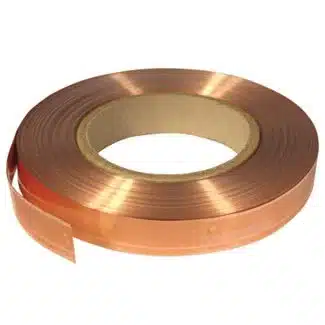
Foil Conductors

Composed of flat strips, they excel at reducing skin losses due to their larger surface area. The flattened shape provides improved current distribution and decreases energy dissipation. Proximity losses can be controlled by proper insulation and spacing between adjacent foil conductors.

Figure 5. Foil conductors

By considering the characteristics of each wire type, such as the distribution of current and magnetic interactions, you can make mindful choices to optimize winding designs and minimize both skin and proximity losses. Understanding how these different wire configurations impact losses is vital for achieving enhanced efficiency in transformers and inductors.

Conclusion

In conclusion, understanding and addressing winding losses, in particular skin and proximity losses, is essential for optimizing the efficiency and performance of Transformers and Inductors.

  • Skin losses occur due to the concentration of current on the outer surface of the wire, leading to underutilization of the inner layers and energy dissipation.
  • Minimizing skin losses can be achieved through techniques like using Litz wire, which evenly distributes the current across multiple insulated strands.
  • Proximity losses arise when magnetic fields from adjacent windings interact, causing energy losses.
  • Proper insulation between windings helps reduce magnetic coupling and mitigate proximity losses.
  • The choice of wire configuration also plays a significant role in minimizing losses. Litz wire, rectangular wires, and foil conductors offer advantages in reducing skin losses, while proper positioning and insulation can mitigate proximity losses. Understanding the characteristics of different wire types allows for informed choices in optimizing winding designs.

By addressing these losses, we can enhance the efficiency and performance of magnetic components, ensuring their optimal operation.

Related

Source: Frenetic

Recent Posts

Bourns Releases Automotive 1W Flyback Transformer

19.5.2025
5

Inductor Resonances and its Impact to EMI

16.5.2025
20

Würth Elektronik Releases High Performance TLVR Coupled Inductors

15.5.2025
23

Causes of Oscillations in Flyback Converters

15.5.2025
18

TDK Unveils Industry Highest Rated Current Multilayer Chip Beads

14.5.2025
19

How to design a 60W Flyback Transformer

12.5.2025
31

Murata Releases 008004 High-Frequency SMD Chip Inductor

12.5.2025
22

Modeling and Simulation of Leakage Inductance

9.5.2025
29

Power Inductor Considerations for AI High Power Computing – Vishay Video

9.5.2025
28

TAIYO YUDEN Releases Compact SMD Power Inductors for Automotive Application

9.5.2025
19

Upcoming Events

May 28
16:00 - 17:00 CEST

Power Over Data Line

View Calendar

Popular Posts

  • Buck Converter Design and Calculation

    0 shares
    Share 0 Tweet 0
  • Flyback Converter Design and Calculation

    0 shares
    Share 0 Tweet 0
  • Boost Converter Design and Calculation

    0 shares
    Share 0 Tweet 0
  • Why Low ESR Matters in Capacitor Design

    0 shares
    Share 0 Tweet 0
  • LLC Resonant Converter Design and Calculation

    0 shares
    Share 0 Tweet 0
  • What is a Dielectric Constant and DF of Plastic Materials?

    4 shares
    Share 4 Tweet 0
  • Ripple Current and its Effects on the Performance of Capacitors

    3 shares
    Share 3 Tweet 0
  • SEPIC Converter Design and Calculation

    0 shares
    Share 0 Tweet 0
  • Flying Capacitors Explained

    0 shares
    Share 0 Tweet 0
  • Dual Active Bridge (DAB) Topology Explained

    0 shares
    Share 0 Tweet 0

Newsletter Subscription


Passive Components Blog

© EPCI - Leading Passive Components Educational and Information Site

  • Home
  • Privacy Policy
  • EPCI Membership & Advertisement
  • About

No Result
View All Result
  • Home
  • Knowledge Blog
  • Premium Suppliers

© EPCI - Leading Passive Components Educational and Information Site

This website uses cookies. By continuing to use this website you are giving consent to cookies being used. Visit our Privacy and Cookie Policy.
Go to mobile version