Passive Components Blog
No Result
View All Result
  • Home
  • NewsFilter
    • All
    • Aerospace & Defence
    • Antenna
    • Applications
    • Automotive
    • Capacitors
    • Circuit Protection Devices
    • electro-mechanical news
    • Filters
    • Fuses
    • Inductors
    • Industrial
    • Integrated Passives
    • inter-connect news
    • Market & Supply Chain
    • Market Insights
    • Medical
    • Modelling and Simulation
    • New Materials & Supply
    • New Technologies
    • Non-linear Passives
    • Oscillators
    • Passive Sensors News
    • Resistors
    • RF & Microwave
    • Telecommunication
    • Weekly Digest

    Samsung Releases Automotive Molded 2220 1kV C0G MLCC

    How to Select Ferrite Bead for Filtering in Buck Boost Converter

    VINATech Offers Smallest 100µF Al-Hybrid Capacitor

    Vishay Unveils SMD 1200V PTC Thermistors in Compact Size

    Power Inductors Future: Minimal Losses and Compact Designs

    Bourns Unveils Automotive 3 Watt Gate Driver Transformer

    Murata Opens EMC Test Lab in Nuremberg to Enhance Automotive Support

    Percolation Phenomenon: Degradation of Molded Power Inductors in DC/DC Converters

    Molex Acquires Smiths Interconnect

    Trending Tags

    • Ripple Current
    • RF
    • Leakage Current
    • Tantalum vs Ceramic
    • Snubber
    • Low ESR
    • Feedthrough
    • Derating
    • Dielectric Constant
    • New Products
    • Market Reports
  • VideoFilter
    • All
    • Antenna videos
    • Capacitor videos
    • Circuit Protection Video
    • Filter videos
    • Fuse videos
    • Inductor videos
    • Inter-Connect Video
    • Non-linear passives videos
    • Oscillator videos
    • Passive sensors videos
    • Resistor videos

    How to Select Ferrite Bead for Filtering in Buck Boost Converter

    Power Inductors Future: Minimal Losses and Compact Designs

    Percolation Phenomenon: Degradation of Molded Power Inductors in DC/DC Converters

    Connector PCB Design Challenges

    Efficient Power Converters: Duty Cycle vs Conduction Losses

    Ripple Steering in Coupled Inductors: SEPIC Case

    SEPIC Converter with Coupled and Uncoupled Inductors

    Coupled Inductors in SEPIC versus Flyback Converters

    Non-Linear MLCC Class II Capacitor Measurements Challenges

    Trending Tags

    • Capacitors explained
    • Inductors explained
    • Resistors explained
    • Filters explained
    • Application Video Guidelines
    • EMC
    • New Products
    • Ripple Current
    • Simulation
    • Tantalum vs Ceramic
  • Knowledge Blog
  • Suppliers
    • Who is Who
  • PCNS
    • PCNS 2025
    • PCNS 2023
    • PCNS 2021
    • PCNS 2019
    • PCNS 2017
  • Events
No Result
View All Result
Passive Components Blog
No Result
View All Result

Snubber Capacitor Selection for SiC-Based Switching Converters

24.8.2022
Reading Time: 4 mins read
A A

The blog article published by Knowles Precision Devices provides guidance on how to select the optimal snubber capacitor for SiC-based switching converters.

Today, most converter circuits now include semiconductors and switches made of silicon carbide (SiC) instead of plain old silicon (Si). This is because when silicon and carbon are combined, the resulting material, SiC, has excellent mechanical, chemical, and thermal properties. Therefore, SiC-based converters can handle voltages up to 10 times greater than converters using just Si while also offering lower losses.

RelatedPosts

Knowles Releases High Q Non-Magnetic X7R MLCCs for Medical Imaging

Knowles Unveils High-Performance Safety-Certified MLCC Capacitors

Knowles Releases Inductors for Mission-Critical RF Applications

These characteristics make these converters an excellent option for applications such as power electronics, industrial devices, and electric vehicle (EV) charging stations. In this first post, we dive into the advantages of using snubber circuits to protect SiC-based converters and discuss how to further increase these efficiencies by focusing on capacitor selection.

Using Snubber Circuits for SiC Switching Converters

When switching occurs quickly, dv/dt and di/dt increase, which, when coupled with stray inductance, can result in a large surge voltage and/or current. To be sure you do not exceed the maximum rated voltage/current of the device, a method to control surge voltage and current is needed. One efficient way to do this is to use a snubber circuit. Using a snubber circuit in a switching converter offers the following benefits:

  • Protecting against voltage and/or current spikes
  • Reducing dv/dt and di/dt
  • Smoothing out ringing
  • Keeping loads in safe operating condition range
  • Minimizing losses, oscillation effects, and electromagnetic interference (EMI)
  • Transferring power dissipation

When using SiC as a base material for power switching device, these benefits are magnified as SiC provides the following benefits over using just Si:

  • Higher thermal conductivity to provide more efficient heat transfer
  • Lower leakage currents
  • Ability to withstand a voltage gradient that is more than eight times higher, enabling components to withstand higher voltages in the same package
  • Greater switching frequencies

Different Snubber Circuit Configurations

There are multiple ways to build a snubber circuit in a converter. Figure 1 shows four common configurations.

Figure 1. Diagrams of the four most common snubber circuit configurations with snubber capacitors suitable for SiC converters – (a) C snubber, (b) RC snubber, (c) Discharge RCD snubber, (d) Non-discharge RCD snubber. Source.

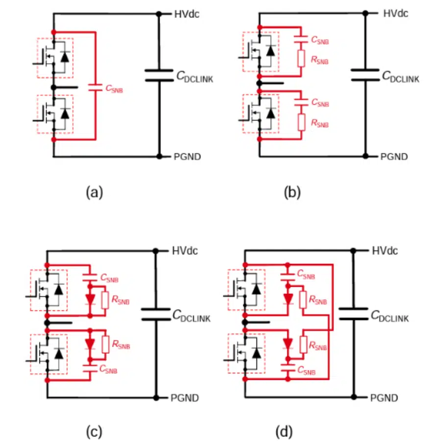
Let’s explore each of these configurations a little more. A C snubber has a simpler design that does not include a resistor and is best suited for 2-in-1 modules instead of circuits with discrete components. An RC snubber adds a resistor into the circuit and the energy stored in CSNB must be dissipated by RSNB during each switching transient. Having the resistor in the snubber circuit protects the circuit against larger di/dt as it reduces the discharge current of the capacitor.

For higher power applications, a diode can be added to create an RCD snubber where the diode is used to block current in the network as the transistor turns on. There are two different types of RCD snubbers – discharge and non-discharge. With a discharge RCD snubber, the surge current flows through the diode and makes CSNB absorption more effective than it is in an RC snubber. A non-discharge RCD snubber only consumes energy from the surge voltage, which means the energy consumption at RSNB does not increase a lot at high switching frequencies.

Considerations for Selecting the Right Capacitor for Snubber Circuits

Whether you are designing a snubber for SiC, Si, or GaN technology, as shown in Figure 1, all snubber circuit configurations include a snubber capacitor. However, since SiC has very different characteristics than Si or GaN and is frequently used for applications that need to operate at high voltages and currents, understanding how to select the most appropriate capacitor is crucial.

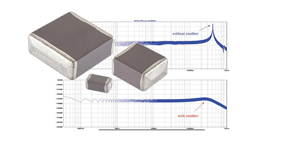
Snubber capacitors for SiC-based circuits typically have smaller capacitance values and need to sit close to the switches to reduce wire inductance. Therefore, specifications for these capacitors that need to be taken into consideration include the package size and type, dielectric, electrode type, voltage and capacitance range, and Irms. Since SiC parts also tend to run hot, the snubber capacitor must be heat tolerant.

MLCC class 1 ceramic capacitors offer high stability in the form of C0G dielectrics, and can achieve high capacitance and high voltage as seen  optimal snubber capacitor for SiC-based circuits. The capacitors’ portfolio offers a wide range of voltages, from 630V to above 4kV, that can be readily used as snubbers to match the voltage rating of existing high-performance SiC devices in the market. 

See also article: RC snubber design for SMPS protection.

Related

Source: Knowles Precision Devices

Recent Posts

Samsung Releases Automotive Molded 2220 1kV C0G MLCC

23.10.2025
21

How to Select Ferrite Bead for Filtering in Buck Boost Converter

23.10.2025
27

VINATech Offers Smallest 100µF Al-Hybrid Capacitor

23.10.2025
32

Power Inductors Future: Minimal Losses and Compact Designs

22.10.2025
35

Percolation Phenomenon: Degradation of Molded Power Inductors in DC/DC Converters

21.10.2025
33

Murata Integrates Component Models into Cadence EDA Tools

21.10.2025
39

High Energy Density Polymer Film Capacitors via Molecular and Interfacial Design

15.10.2025
26

KYOCERA AVX Expands Stacked MLCC Capacitors Offering

14.10.2025
45

Over-Voltage Protection Clippers, Clampers, Snubbers, DC Restorers

13.10.2025
33

Silicon Capacitors Market: Shaping the Foundation for Next-Gen Miniaturization Electronics

10.10.2025
80

Upcoming Events

Oct 28
8:00 - 15:00 CET

Power Up Your Design: SN6507 and the Ready-to-Use Development Kit

Oct 30
11:00 - 12:00 CET

Space Ceramic Capacitors with Flexible Testing

Nov 4
10:00 - 11:00 PST

Design and Stability Analysis of GaN Power Amplifiers using Advanced Simulation Tools

View Calendar

Popular Posts

  • Buck Converter Design and Calculation

    0 shares
    Share 0 Tweet 0
  • Boost Converter Design and Calculation

    0 shares
    Share 0 Tweet 0
  • Flyback Converter Design and Calculation

    0 shares
    Share 0 Tweet 0
  • LLC Resonant Converter Design and Calculation

    0 shares
    Share 0 Tweet 0
  • Ripple Current and its Effects on the Performance of Capacitors

    3 shares
    Share 3 Tweet 0
  • What is a Dielectric Constant and DF of Plastic Materials?

    4 shares
    Share 4 Tweet 0
  • SEPIC Converter Design and Calculation

    0 shares
    Share 0 Tweet 0
  • Dual Active Bridge (DAB) Topology

    0 shares
    Share 0 Tweet 0
  • MLCC and Ceramic Capacitors

    0 shares
    Share 0 Tweet 0
  • Flying Capacitors

    0 shares
    Share 0 Tweet 0

Newsletter Subscription


Passive Components Blog

© EPCI - Leading Passive Components Educational and Information Site

  • Home
  • Privacy Policy
  • EPCI Membership & Advertisement
  • About

No Result
View All Result
  • Home
  • Knowledge Blog
  • PCNS

© EPCI - Leading Passive Components Educational and Information Site

This website uses cookies. By continuing to use this website you are giving consent to cookies being used. Visit our Privacy and Cookie Policy.
Go to mobile version