Passive Components Blog
No Result
View All Result
  • Home
  • NewsFilter
    • All
    • Aerospace & Defence
    • Antenna
    • Applications
    • Automotive
    • Capacitors
    • Circuit Protection Devices
    • electro-mechanical news
    • Filters
    • Fuses
    • Inductors
    • Industrial
    • Integrated Passives
    • inter-connect news
    • Market & Supply Chain
    • Market Insights
    • Medical
    • Modelling and Simulation
    • New Materials & Supply
    • New Technologies
    • Non-linear Passives
    • Oscillators
    • Passive Sensors News
    • Resistors
    • RF & Microwave
    • Telecommunication
    • Weekly Digest

    Smolteks CNF MIM Capacitor Break 1 µF/mm²

    Samsung Electro-Mechanics Releases 0201 X7T 1uF 6.3V MLCC for ADAS Applications

    Murata Announces 0402 Automotive Chip Ferrite Beads for V2X

    2025 Thick and Thin Film Resistor Networks Environment Overview

    Role of High-Q Ceramic Filters to Overcome GNSS Jamming

    Optimization of IoT for GEO NB-NTN Hybrid Connectivity

    TDK Releases Automotive Power-Over-Coax Inductor for Filters

    Advanced Conversion Announces Mass Production of 200C Film Capacitors

    VinaTech Supercapacitors: Enhancing Smart Meter Reliability and Efficiency

    Trending Tags

    • Ripple Current
    • RF
    • Leakage Current
    • Tantalum vs Ceramic
    • Snubber
    • Low ESR
    • Feedthrough
    • Derating
    • Dielectric Constant
    • New Products
    • Market Reports
  • VideoFilter
    • All
    • Antenna videos
    • Capacitor videos
    • Circuit Protection Video
    • Filter videos
    • Fuse videos
    • Inductor videos
    • Inter-Connect Video
    • Non-linear passives videos
    • Oscillator videos
    • Passive sensors videos
    • Resistor videos

    Understanding Switched Capacitor Converters

    Coupled Inductors Circuit Model and Examples of its Applications

    Inductor Resonances and its Impact to EMI

    Highly Reliable Flex Rigid PCBs, Würth Elektronik Webinar

    Causes of Oscillations in Flyback Converters

    How to design a 60W Flyback Transformer

    Modeling and Simulation of Leakage Inductance

    Power Inductor Considerations for AI High Power Computing – Vishay Video

    Coupled Inductors in Multiphase Boost Converters

    Trending Tags

    • Capacitors explained
    • Inductors explained
    • Resistors explained
    • Filters explained
    • Application Video Guidelines
    • EMC
    • New Products
    • Ripple Current
    • Simulation
    • Tantalum vs Ceramic
  • Knowledge Blog
  • Suppliers
    • Who is Who
  • Events
No Result
View All Result
Passive Components Blog
No Result
View All Result

Solder Paste Volume

12.9.2021
Reading Time: 3 mins read
A A

The solder paste volume on the PCB surface will be determined by the thickness and area of the stencil opening. Stencil thickness is in the 100 to 200 micron range, and the area will depend on the PCB design. Typical stencil apertures are shown in Figure 2.88.

Fig. 2.88: Typical stencil apertures

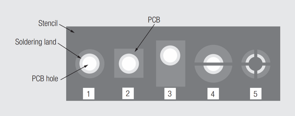
Apertures 1 & 2 are typical for THR printing.
Aperture 3 is used when extra solder paste is needed.
Aperture 4 (paste reducer) is used for large PCB PTHs to prevent the solder paste from dropping through the PTH.
Aperture 5 is commonly used when double printing, top and bottom of the PCB, to add additional solder paste to meet the solder requirement.

RelatedPosts

Polymer Materials and Processing

What is RF Connector

Connector Materials and Processes

Typical PCB pad dimensions are shown in Figure 2.89, where Tb is the PCB thickness, generally 1.6 mm, Dd is the drilled hole diameter (not shown), Dh is the PCB PTH. Dh = Dp + 0.3 mm, where Dp is the pin diameter (shown in Figure 2.89) and Dsp is the solder pad diameter = Dh + 0.5 mm to 0.8 mm.

Fig. 2.89: PCB pad dimensions
Fig. 2.90: Pin diameter

The stencil area, as shown in Figure 2.91, in combination with the stencil thickness (Ts), determines the solder paste volume on the surface of the PCB. Ideally, when an overprint is not necessary, the stencil diameter (Ds ) = Dsp – 0.1 in order to guarantee a perfect paste deposition on the solder pad.

Fig. 2.91: Stencil dimensions

As noted previously, the solder paste consists of approximately 50 percent of the volume of solder particles and 50 percent of the soldering flux volume. The optimum solder particle size depends on the pitch of the PCB pads and on the thickness of the stencil. If the particle size is too large, as per Figure 2.92, the effective solder volume will be reduced.

Fig. 2.92: Effect of the solder particle size on stencil fill

If the solder particle size is too small, viscosity issues may arise, thus affecting the retention of the solder paste in the stencil. The most commonly used solder particle size is in the range of 20 to 45 microns. JEDEC STD-005 covers soldering paste requirements. The pin geometry, square, round or rectangular, may also impact the stencil fill and the solder volume.

Related

Source: Wurth elektronik

Recent Posts

Non-Magnetic Interconnects

23.4.2025
22

10 Tips for Ensuring Reliability of Discrete Wire Assemblies

20.2.2025
53

Polymer Materials and Processing

31.1.2025
38

Basic PCB Technology Overview

17.12.2024
15

What is RF Connector

17.12.2024
7

Creepage and Clearance of Connector

16.10.2023
14

Microwave Multi Line Connectors Mounting and Handling Precautions

17.12.2024
2

BASIC PCB Design Rules – Layout

17.12.2024
24

MEMR RF Relay for Space Compact Redundancy Ring

17.12.2024
2

Connector Temperature Rise and Derating

13.1.2023
17

Upcoming Events

Jun 24
16:00 - 17:00 CEST

Limitations of PSFB converters and improvements by a variable inductor ft. Sam Ben-Yaakov

Jun 24
17:00 - 18:00 CEST

Ultra-Compact and Efficient Switched-Capacitor Power Converters

Jul 23
13:00 - 14:00 CEST

PCB design for a Smartwatch

View Calendar

Popular Posts

  • Buck Converter Design and Calculation

    0 shares
    Share 0 Tweet 0
  • Boost Converter Design and Calculation

    0 shares
    Share 0 Tweet 0
  • Flyback Converter Design and Calculation

    0 shares
    Share 0 Tweet 0
  • What is a Dielectric Constant and DF of Plastic Materials?

    4 shares
    Share 4 Tweet 0
  • LLC Resonant Converter Design and Calculation

    0 shares
    Share 0 Tweet 0
  • Ripple Current and its Effects on the Performance of Capacitors

    3 shares
    Share 3 Tweet 0
  • How to Design an Inductor

    0 shares
    Share 0 Tweet 0
  • SEPIC Converter Design and Calculation

    0 shares
    Share 0 Tweet 0
  • Dual Active Bridge (DAB) Topology Explained

    0 shares
    Share 0 Tweet 0
  • Why Low ESR Matters in Capacitor Design

    0 shares
    Share 0 Tweet 0

Newsletter Subscription


Passive Components Blog

© EPCI - Leading Passive Components Educational and Information Site

  • Home
  • Privacy Policy
  • EPCI Membership & Advertisement
  • About

No Result
View All Result
  • Home
  • Knowledge Blog
  • Premium Suppliers

© EPCI - Leading Passive Components Educational and Information Site

This website uses cookies. By continuing to use this website you are giving consent to cookies being used. Visit our Privacy and Cookie Policy.
Go to mobile version