Passive Components Blog
No Result
View All Result
  • Home
  • NewsFilter
    • All
    • Aerospace & Defence
    • Antenna
    • Applications
    • Automotive
    • Capacitors
    • Circuit Protection Devices
    • electro-mechanical news
    • Filters
    • Fuses
    • Inductors
    • Industrial
    • Integrated Passives
    • inter-connect news
    • Market & Supply Chain
    • Market Insights
    • Medical
    • Modelling and Simulation
    • New Materials & Supply
    • New Technologies
    • Non-linear Passives
    • Oscillators
    • Passive Sensors News
    • Resistors
    • RF & Microwave
    • Telecommunication
    • Weekly Digest

    5th PCNS Awards Outstanding Passive Component Papers

    TDK Releases Ultra-small PFC Capacitors

    KYOCERA AVX Releases Novel Mini BME Stacked Ceramic Capacitors

    Vishay Releases Class 1 Leaded High Voltage Ceramic Disc Capacitors

    TDK Releases 140C Compact Vibration Robust Automotive Aluminum Capacitors

    DigiKey Presents Factory Tomorrow Season 5 Video Series

    Samsung MLCCs Lineup for In-Vehicle Infotainment

    source: Samtec

    Best Practices for Cable Management in High-Speed and High-Density Systems

    Würth Elektronik Unveils Compact Common-Mode Data Lines Chokes

    Trending Tags

    • Ripple Current
    • RF
    • Leakage Current
    • Tantalum vs Ceramic
    • Snubber
    • Low ESR
    • Feedthrough
    • Derating
    • Dielectric Constant
    • New Products
    • Market Reports
  • VideoFilter
    • All
    • Antenna videos
    • Capacitor videos
    • Circuit Protection Video
    • Filter videos
    • Fuse videos
    • Inductor videos
    • Inter-Connect Video
    • Non-linear passives videos
    • Oscillator videos
    • Passive sensors videos
    • Resistor videos

    Ripple Steering in Coupled Inductors: SEPIC Case

    SEPIC Converter with Coupled and Uncoupled Inductors

    Coupled Inductors in SEPIC versus Flyback Converters

    Non-Linear MLCC Class II Capacitor Measurements Challenges

    Percolation Phenomenon and Reliability of Molded Power Inductors in DC/DC converters

    Root Causes and Effects of DC Bias and AC in Ceramic Capacitors

    How to Calculate the Output Capacitor for a Switching Power Supply

    Switched Capacitor Converter Explained

    Understanding Inductor Dot Markings and Their Application in LTspice

    Trending Tags

    • Capacitors explained
    • Inductors explained
    • Resistors explained
    • Filters explained
    • Application Video Guidelines
    • EMC
    • New Products
    • Ripple Current
    • Simulation
    • Tantalum vs Ceramic
  • Knowledge Blog
  • Suppliers
    • Who is Who
  • Events
No Result
View All Result
Passive Components Blog
No Result
View All Result

Sumida High current SMD type Inductor for Automotive applications

5.7.2017
Reading Time: 10 mins read
A A

source: Sumida news

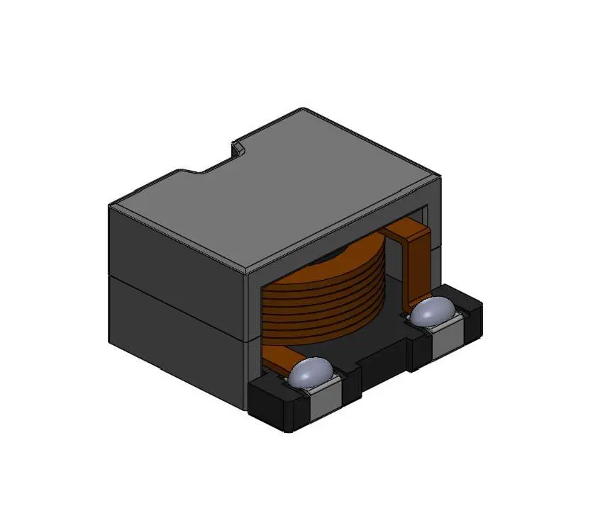
This SMD power inductor series is wound by flat wire and assembled with a Mn-Zn ferrite core. The L values range (lower side) of the existing CDEP15D90/T150 and newly developed 13mm sq. CDEP13D76/T150 was expanded. To meet the high power handling and high insulation voltage demand for automotive applications, the CDEPxxDxx/T150 series which would correspond to high insulation voltage (DC120V) was developed.

RelatedPosts

5th PCNS Awards Outstanding Passive Component Papers

TDK Releases Ultra-small PFC Capacitors

KYOCERA AVX Releases Novel Mini BME Stacked Ceramic Capacitors

The product family family of CDEPxxxxT150 will continue to be further developed in order to expand Sumida’s product portfolio and to fulfil the increasing demand from the market.

Key Features

  • AEC-Q200 qualified
  • Secured insulation voltage between core and coil (max 120Vdc)
  • Operational Temperature range:  -40°C ~ +150°C (including self-heating)

Applications

  • LED head lighting
  • ECU & other high power supply applications for automotive

Electrical Characteristics – CDEP13D76/T150:  Standard Types

Part Name  Inductance
(µH)(±20%)
※1 
D.C.R(mΩ) (±20%)  Saturation Current (A) ※2
Temperature Rise Currrent
(A) ※3 
at 20°C   at 150°C
CDEP13D76T150NP-1R0MC 105 1.00 1.98 31.0 21.0 20.0
CDEP13D76T150NP-1R6MC 105 1.60 2.60 25.0 17.0 17.8
CDEP13D76T150NP-2R4MC 105 2.40 3.30 21.0 15.0 16.1
CDEP13D76T150NP-3R6MC 105 3.60 3.90 17.2 11.5 15.0
CDEP13D76T150NP-5R1MC 105 5.10 4.80 14.6 10.3 13.0
CDEP13D76T150NP-6R8MC 105 6.80 5.90 12.7 9.00 11.5
CDEP13D76T150NP-100MC 105 10.0  10.3 10.5 7.30 8.50
CDEP13D76T150NP-120MC 105 12.5  13.4 9.30  6.50 7.50
CDEP13D76T150NP-150MC 105  15.0 15.2 8.50 6.20 7.00
CDEP13D76T150NP-220MC 105 22.0  23.4 6.90 4.70 5.30


Electrical Characteristics – CDEP13D76/T150:  High Power Types

Part Name  Inductance
(µH)(±20%)
※1
D.C.R(mΩ) (±20%)  Saturation Current (A) ※2
Temperature Rise Currrent
(A) ※3 
at 20°C   at 150°C
CDEP13D76T150NP-0R8MC-90 0.80 1.98 40.0 27.0 20.0
CDEP13D76T150NP-1R5MC-90 1.50 2.60 28.5 19.0 17.8
CDEP13D76T150NP-2R2MC-90 2.20 3.30 24.5 16.5 16.1
CDEP13D76T150NP-3R3MC-90 3.30 3.90 19.4 14.2 15.0
CDEP13D76T150NP-4R3MC-90 4.30 4.80 17.2 12.2 13.0
CDEP13D76T150NP-6R8MC-90 6.80 7.40 13.7 9.50 10.0
CDEP13D76T150NP-100MC-90 10.0  13.4 11.3 7.70 7.50
CDEP13D76T150NP-120MC-90 12.5  15.2 10.2 7.20 7.00
CDEP13D76T150NP-150MC-90 15.0 19.9 9.30 6.50 6.00
CDEP13D76T150NP-220MC-90 22.0  30.4 7.50 5.40 4.70


Electrical Characteristics – CDEP15D90/T150:  Standard Types

Part Name  Inductance
(µH)(±20%)
※1 
D.C.R(mΩ) (±20%)  Saturation Current (A)  ※2
Temperature Rise Currrent
(A) ※3 
at 20°C   at 150°C
CDEP15D90T150NP-0R5MC-125 0.50 1.20 63.0 43.0 33.5
CDEP15D90T150NP-1R2MC-125 1.20 1.75 41.9 28.5 24.5
CDEP15D90T150NP-2R0MC-125 2.00 2.40 31.0 22.0 23.0
CDEP15D90T150NP-3R3MC-125 3.30 2.90 25.0 17.0 18.5
 CDEP15D90T150NP-4R7MC-125  4.70 3.50   21.2 14.8  16.5 
CDEP15D90T150NP-6R2MC-125   6.20 4.90   18.5 13.0  14.8 
 CDEP15D90T150NP-100MC-125 10.0   7.90 15.0  10.4   12.5
CDEP15D90T150NP-120MC-125  12.5  8.90  12.8   9.50  12.2
 CDEP15D90T150NP-150MC-125  15.0  10.6 12.0  8.40   8.50
CDEP15D90T150NP-220MC-125  22.0   14.5 9.60  6.60   7.50


Electrical Characteristics – CDEP15D90/T150:  High Power Types

Part Name  Inductance
(µH)(±20%)
※1
D.C.R(mΩ) (±20%)  Saturation Current (A) ※2
Temperature Rise Currrent
(A) ※3 
at 20°C   at 150°C
CDEP15D90T150NP-1R0MC-100 1.00 1.75 51.6 35.8 24.5
CDEP15D90T150NP-1R6MC-100 1.60 2.40 42.0 28.0 23.0
CDEP15D90T150NP-2R4MC-100 2.40 2.90 34.5 24.5 18.5
CDEP15D90T150NP-3R6MC-100 3.60 3.50 26.5 18.5 16.5
 CDEP15D90T150NP-4R7MC-100 4.70 4.90 24.0 16.6 14.8
CDEP15D90T150NP-6R8MC-100 6.80 5.50 20.4 13.8 13.5
 CDEP15D90T150NP-100MC-100 10.0  8.90 16.3 11.6 12.2
CDEP15D90T150NP-120MC-100 12.5  10.6 15.0 10.3 8.50
 CDEP15D90T150NP-150MC-100 15.0 13.4 13.4 9.60 8.00
CDEP15D90T150NP-220MC-100 22.0  20.1 11.0 7.50 6.50

※ 1 Measuring frequency at 100kHz 0.1V
※ 2 Saturation current: This indicates the actual value of D.C. current when the inductance becomes 30% lower than its nominal value.
※ 3 Temperature rise current: The actual value of D.C. current when the temperature of coil becomes △T=40°C (Ta=20°C).

Please note that when using the product while applying current with audio-frequency (AF) signals may results in audible noises due to magnetostriction. Also, in order to avoid an audible noise problem, operating with non-AF signals would be recommended. The noise amplify depending on the coil mount area on the PCB.

Production

CDEP13D76/T150:  in July 2017
CDEP15D90/T150:  in series production
(Note: Though all samples are available now, series production for below 4.7uH L values parts for both types will be launched the series production in Q4 2017.)

Related

Recent Posts

5th PCNS Awards Outstanding Passive Component Papers

14.9.2025
2

TDK Releases 140C Compact Vibration Robust Automotive Aluminum Capacitors

5.9.2025
28

Samsung MLCCs Lineup for In-Vehicle Infotainment

4.9.2025
27

Würth Elektronik Unveils Compact Common-Mode Data Lines Chokes

3.9.2025
30

Littelfuse Adds 600W Automotive TVS Diodes for High-Energy Transient Protection

2.9.2025
13

Vishay Releases Harsh Environment Robust DC-Link Film Capacitor

2.9.2025
38

Bourns Releases Automotive High Creepage and Clearance Transformer

1.9.2025
31

Bourns Unveils Metal Powder Core High Current Low DCR Shielded Power Inductor

29.8.2025
35

Modelithics Release Discrete Components Optimization Article for RF/Microwave Designers

28.8.2025
15

Samsung Extends Capacitance of MLCC 0805 X7T 250V to 100nF

28.8.2025
34

Upcoming Events

Sep 16
17:00 - 18:00 CEST

EMI Shielding Challenges

Sep 22
September 22 @ 13:00 - September 25 @ 15:15 EDT

Pre Cap Visual Inspection per Mil-Std-883 (TM 2017)

Sep 30
September 30 @ 12:00 - October 2 @ 14:00 EDT

MIL-Std-883 TM 2010

Oct 17
12:00 - 14:00 EDT

External Visual Inspection per MIL-STD-883 TM 2009

Oct 20
October 20 - October 23

Digital WE Days 2025 – Virtual Conference

View Calendar

Popular Posts

  • Buck Converter Design and Calculation

    0 shares
    Share 0 Tweet 0
  • Boost Converter Design and Calculation

    0 shares
    Share 0 Tweet 0
  • Flyback Converter Design and Calculation

    0 shares
    Share 0 Tweet 0
  • LLC Resonant Converter Design and Calculation

    0 shares
    Share 0 Tweet 0
  • Dual Active Bridge (DAB) Topology Explained

    0 shares
    Share 0 Tweet 0
  • Ripple Current and its Effects on the Performance of Capacitors

    3 shares
    Share 3 Tweet 0
  • What is a Dielectric Constant and DF of Plastic Materials?

    4 shares
    Share 4 Tweet 0
  • SEPIC Converter Design and Calculation

    0 shares
    Share 0 Tweet 0
  • How to Design an Inductor

    0 shares
    Share 0 Tweet 0
  • Core Materials, Permeability and Their Losses

    0 shares
    Share 0 Tweet 0

Newsletter Subscription


Passive Components Blog

© EPCI - Leading Passive Components Educational and Information Site

  • Home
  • Privacy Policy
  • EPCI Membership & Advertisement
  • About

No Result
View All Result
  • Home
  • Knowledge Blog
  • Premium Suppliers

© EPCI - Leading Passive Components Educational and Information Site

This website uses cookies. By continuing to use this website you are giving consent to cookies being used. Visit our Privacy and Cookie Policy.
Go to mobile version