


This article is a concise version of blog posts by Phil Lessner, Ph.D., a former CTO of KEMET and YAGEO Group, and an independent consultant in the Electronics Component Industry. It offers an overview of the history and evolution of tantalum capacitors and how the capacitors have progressed from wet electrolytes to solid MnO2 types and finally to polymer capacitor types. Published under the author’s permission.
Tantalum Capacitors Wet and Solid Electrolyte Technology Background
Tantalum capacitors, one of the five main capacitor dielectric types in modern electronics, have a history spanning nearly a century. Their use surged after the invention of the solid tantalum capacitor during the transistor era. This blog post traces their development and application since then. As tantalum capacitors are still evolving for future applications, the final post will discuss their future directions and challenges.
Tantalum capacitors, introduced over 90 years ago by Fansteel and Tansitor, are polar devices with tantalum metal as the positive electrode (anode) and a wet electrolyte or a solid semiconductor as the negative electrode (cathode). Tantalum pentoxide (Ta2O5) serves as the dielectric.
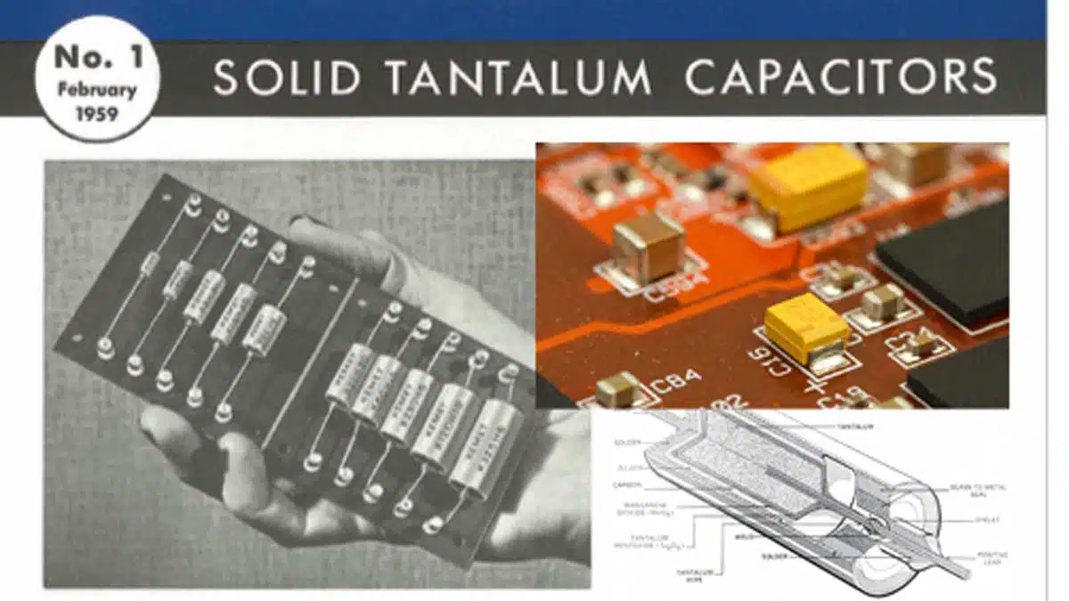
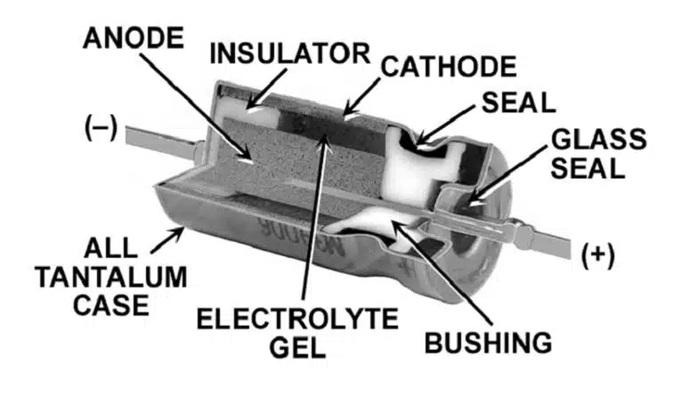
Wet tantalum capacitors, introduced in the past as replacements for aluminum electrolytic capacitors in demanding applications due to their smaller size and higher reliability, have a tantalum anode and a dielectric film of tantalum pentoxide formed electrochemically from an ionic solution. The cathode is made from a high surface area tantalum powder or a noble metal compound. They are hermetically sealed in a can with a wire for contact. See Figure 1. below.
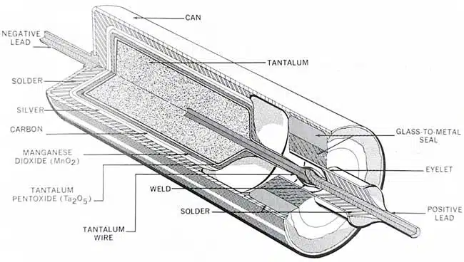
Solid tantalum capacitors (Fig.2.), developed in the mid-1950s, replace the wet electrolyte with a conductive manganese dioxide cathode. The graphite layer prevents reaction between the MnO2 and silver layers. In the thru-hole hermetic seal version, the silver is soldered to a brass can, and a cathode lead is attached. Later developments replaced the solder, can, and other components with thinner layers for increased volumetric efficiency.
Tantalum capacitors share the capacitor market with other types like film, multilayer ceramic, aluminum electrolytic, and super capacitors. They’re chosen for their high capacitance-voltage product (CV), small package size, stable capacitance, and reliability. Equation 1 shows the relationship between CV and the Ta2O5 dielectric properties.

[1]
Tantalum capacitors achieve high capacitance through the area term in Equation 1. Capacitor-grade tantalum powder consists of particle sizes less than 1µm and a surface area exceeding 2m²/g.
The Ta2O5 dielectric withstands high electric fields and has a theoretical breakdown voltage of about 550 V/µm, comparable to Al2O3 and plastic film dielectrics, but higher than crystalline ceramics like barium titanate. In practice, the dielectric strength is derated to achieve the rated voltage.
The solid tantalum capacitor with a manganese dioxide cathode was invented simultaneously by two groups. Dr. Preston Robinson at Sprague Electric in North Adams, USA, described a tantalum capacitor with a lead dioxide cathode in US Patent 3,066,247 (applied in 1954). This capacitor had a “self-healing mechanism” where the semiconductive material was reducible in high fields, and the film-forming metal oxidized to heal imperfections.
This self-healing mechanism is crucial for the reliability of solid tantalum capacitors. No dielectric is perfect, and imperfections exist in tantalum pentoxide due to impurities, crystalline inclusions, oxygen vacancies, and manufacturing stresses. Figure 5 illustrates one healing mechanism. When heated, the semiconductive MnO2 transforms to a non-conductive lower oxide (Mn2O3), forming a plug at the defect. This transformation is facilitated by the leakage current flowing through the defect site. Additionally, oxygen can be donated to the dielectric, neutralizing defects like oxygen vacancies.
R.J. Millard of Sprague Electric described the use of MnO2 in solid tantalum capacitors in US Patent 2,936,514. MnO2 can be impregnated into the sintered tantalum anode by decomposing aqueous manganous nitrate at around 300°C:
Mn(NO3)2 → MnO2 + 2NO2 [2]
This impregnation with aqueous nitrate and heating to convert to oxide covers the entire dielectric surface with the cathode, fully utilizing the ‘A’ term in Equation 1.
Meanwhile, Bell Telephone Laboratories developed a solid tantalum capacitor simultaneously. The four developers were H.E. Haring, R.L. Taylor, D.A. McLean, and F. Power.
Bell Labs’ patent (applied in 1953) describes a solid tantalum capacitor with a semiconductive metal oxide (MnO2). It also proposes ‘reforming’ the dielectric in an electrolyte to lower leakage current and improve capacitor reliability.
Sprague and Bell Labs both claimed inventorship of the solid tantalum capacitor, but their patents remained pending due to a priority dispute. By the early 1960s, the market had grown to $29M, and other companies like KEMET entered the market.
In April 1964, Bell Laboratories acknowledged Sprague Electric’s patent priority, granting Sprague the rights to the growing market. Solid tantalum capacitors found immediate applications in defense, aerospace, and commercial markets, leading to rapid performance advancements.
Improving the Solid Tantalum Capacitor
The solid tantalum capacitor’s invention was timely. The transistor’s introduction led to lower voltages and circuit miniaturization, both of which benefited the capacitor. The space age and manned space missions required highly reliable electronics in vacuum and extreme temperature conditions, making wet electrolytic capacitors unsuitable.
Improvements began in the early 1960s to the solid tantalum capacitor process. One focus was on the amorphous Ta2O5 dielectric formed by electrochemical anodization of the tantalum anode. However, Ta2O5 can lose oxygen, transforming to Ta2O5-x, which is a poorer insulator and causes leakage current increases and failures. Another mechanism of failure is crystallization of the amorphous dielectric, where crystals grow perpendicular to the dielectric plane and cause high leakage currents and failures.
Early on, it was recognized that the high temperature of converting manganese nitrate to manganese dioxide destabilized the dielectric by driving oxygen from it into the Ta anode, creating oxygen vacancies. To partially solve this, Sprague Electric’s Smyth, Shirn, and Tripp discovered that heat treating the Ta/Ta2O5 system at around 400°C and then subjecting it to a second anodization step stabilized the dielectric against some damage caused by the solid cathode deposition. This heat treatment stabilized the Ta/Ta2O5 interface during subsequent high temperature exposure, either during MnO2 deposition or during capacitor operation. The second dielectric anodization step replaced oxygen lost from the dielectric, reducing the number of oxygen vacancies.
Increasing capacitance or ‘downsizing’ involves increasing the surface area of the tantalum powder. Instead of surface area, powder charge, CV/g, or µCoulombs/g is used as a measure.
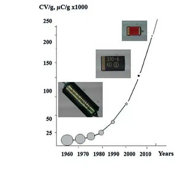
Figure 3. shows the evolution of powder charge. It has increased over an order of magnitude since the 1960s, resulting in smaller case sizes and higher capacitances for tantalum capacitors. Powder purity has also improved, contributing to higher quality dielectrics and more reliable capacitors. Careful control of tantalum particle size has allowed more surface area to be retained as anodization voltage increases, resulting in higher capacitance ratings at higher rated voltages.
To use tantalum powder in capacitors, the particles must be sintered to form a porous anode impregnated with the cathode material. Tantalum forms a passivating film of Ta2O5 on its surface. During vacuum anode sintering, oxygen from this film reacts with tantalum, forming a new passivating film after cooling and re-exposure to air. Controlling oxygen content is crucial to avoid crystallization and uncontrolled passivation, which can lead to crystalline passivation layers and potentially powder burning, especially with higher powder charge.
Dr. Yuri Freeman, while at Vishay (acquired Sprague Electric’s tantalum capacitor business in 1992), collaborated with Tel Aviv University researchers to apply this knowledge and improve tantalum anodes from high-charge powders. His book on tantalum and niobium capacitors is the definitive reference in the field, with the first edition winning the first Ekeberg Prize from the T.I.C. in 2018.
The quality of the dielectric also depends on the anodization chemistry and process, resulting in tantalum pentoxide (Ta2O5). The reaction can be written as:
5Ta + 5H20 → Ta205 + 5H2. [3]
Forming high-quality dielectrics involves several pitfalls. Anodization produces amorphous dielectrics, but incorrect process conditions can lead to crystal formation, causing high leakage current or catastrophic failure under voltage and temperature. Vermilyea’s work in the 1950s highlighted the role of tantalum purity and its effect on crystallization. Early studies showed that phosphorous incorporation improved tantalum capacitor performance under voltage and temperature. Randall et al. at Sprague Electric and Sloppy and Dickey at Penn State provided further insights into phosphorous incorporation.
For the first 35 years of solid tantalum capacitor commercialization, phosphoric acid electrolytes in water or water-ethylene glycol mixtures formed high-quality dielectric films. However, limitations arose with higher charge powders and ethylene glycol emissions. Brian Melody and his group at KEMET Electronics developed new electrolytes, such as near-neutral electrolytes for high-charge powders and polyethylene glycols, replacing ethylene glycol. They also introduced new electrolyte solvents like tetragylme, enabling the formation of thick (high voltage capability) dielectric films.
Manufacturers of tantalum capacitors made significant progress in electrical testing and screening during the 1960s and 70s. They discovered that tantalum capacitors had a declining failure rate with voltage and temperature, leading to factory grading and reliability levels for high-reliability applications.
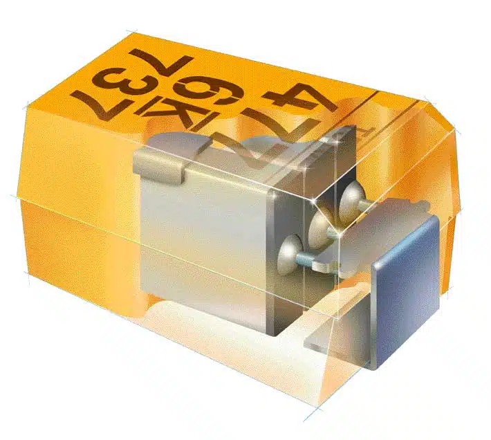
The 1980s and 90s saw the rise of personal computers and mobile phones, increasing electronic device penetration and production demands. Surface mount components, which increased throughput and decreased costs, followed suit. Tantalum capacitor manufacturers adapted, as shown in Figure 4, a cut-away view of a surface mount solid tantalum capacitor.
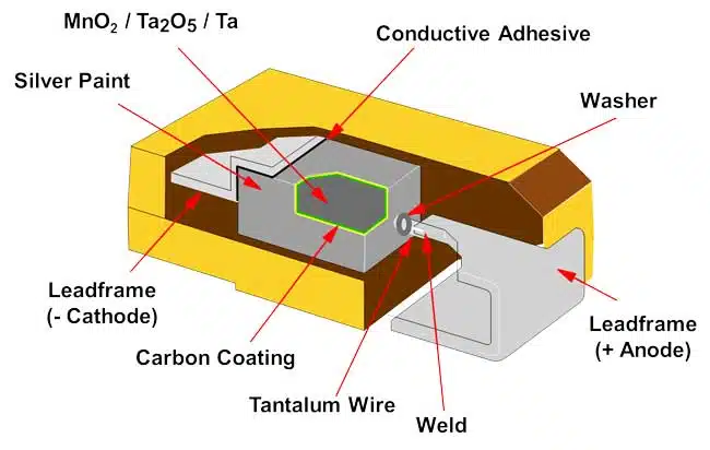
Other surface mount solid tantalum forms exist, but the construction shown in Figure 4. dominates today. Surface mount solid tantalum chips account for about 90% of the market. Thru-hole components are still used in legacy and specialized applications.
The transition from analog to digital electronics resulted in more stringent requirements for powering devices especially as clock speed is increased and voltage levels decreased. Clock speed increases meant higher currents needed to be supplied to the chip and voltage level decreases meant that margin between logic high and logic low was smaller and voltage needed tighter regulation. One of the main uses of solid tantalum capacitors is as a decoupling capacitor in power delivery networks, and to be effective they need to deliver their energy quickly. The rate of energy delivery (power) is limited by the capacitor’s Equivalent Series Resistance (ESR). The semiconductive MnO2 used as the cathode and responsible to the self-healing reliability mechanism in the solid tantalum capacitor has a resistivity of about 0.1-1Ω-cm which is orders of magnitude less conductive than metals such as silver or copper.
Starting in the 1970s concerted efforts were made to reduce the ESR of solid tantalum capacitors. Piper proposed connecting several tantalum capacitors in parallel inside the molded case. This was commercialized by KEMET Electronics in 1997 as the Multiple Anode Tantalum (MAT) and resulted in availability of solid tantalum capacitors with ESR below 30mΩ.
The MAT solution was expensive due to the need for multiple capacitors and part discarding for defective capacitors. Manufacturers like KEMET and AVX developed alternatives like the fluted anode design, which reduced ESR but wasn’t as effective as MAT. See Figures 5. and 6.
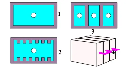
In the 1950s, researchers studied the contributions of solid tantalum capacitor material components to ESR. They found that MnO2 dominated the frequency range of 10s to 100s of kHz, which is relevant for capacitive filtering and bulk decoupling in switching power supplies. Improvements in MnO2 conductivity, especially the β-MnO2 form, were made during this period. Combined with advancements in construction, large case size (7.3×4.3mm) solid tantalum capacitors with ESRs in the 10’s of milliohms were achieved. These electrical properties were translated into Spice models for circuit design.
Digital circuit speeds increased and voltage levels dropped by the mid-1990s. Even advanced Tantalum capacitors with manganese dioxide cathodes struggled to meet design requirements. Multi-layer ceramic capacitors (MLCC) began to challenge Tantalum’s dominance, especially in portable devices due to the cost-effectiveness of nickel electrodes. Tantalum capacitor use would have declined except for a breakthrough in conductive materials in the 1970s and its application to solid Tantalum capacitors starting in the 1990s.
Conducting Polymer Cathodes
Polymers are considered insulating materials, but conducting polymers, discovered in the late 1970, could be electrically conductive with conjugated structures and certain doped molecules. Shirakawa, MacDiarmid, and Heeger’s discovery led to the Nobel Prize in 2000.
Though less conductive than metals, conductive polymers were far more conductive than inorganic semiconductors like manganese dioxide. Like manganese dioxide, they became non-conductive (or ‘burned away’) upon high-temperature heating, offering self-healing capabilities at dielectric fault sites. However, polyacetylene’s instability in air limited its practical use.
Research led to the development of more stable conductive polymers, including polypyrrole (PPy) and polyethylenedioxythiophene (PEDOT). The first commercially successful capacitor with a conducting polymer cathode, an aluminum electrolytic capacitor, was introduced by Matsushita (Panasonic) in 1991, featuring PPy deposited by electrodeposition.
NEC’s Energy Devices Division followed with a tantalum capacitor, NEOCAPACITOR, based on chemically deposited PPy. A second-generation device based on PEDOT, developed by Dr. Fredrich Jonas and colleagues at Bayer AG, was introduced a few years later.
The substitution of conductive polymer for manganese dioxide as the cathode material had a dramatic impact on the ESR of the tantalum capacitor. Devices with ESRs below 30mΩ could be manufactured with single anodes instead of the more costly MAT construction and with a MAT single digit ESR could be achieved. Due to continuing material advances over the last 30 years, single digit ESRs are possible even with single anodes in 7.3×4.3mm case sizes and small case size ESRs below 50mΩ are possible.
Capacitor manufacturers recognized the potential of the “Tantalum-Polymer” capacitor. Sanyo entered the market with its POSCAP device, while KEMET Electronics signed a licensing/co-development agreement with NEC in 1998. The new capacitor was called “KO-CAP” by KEMET.
Lower ESR was the main benefit of Tantalum-Polymer capacitors, but other advantages over traditional manganese dioxide solid tantalum capacitors were soon discovered. The internal ESR was lower, so capacitance decreased less with increasing frequency, allowing Tantalum-Polymer capacitors to be used in higher frequency circuits. Tantalum-MnO2 capacitors had a reputation for ‘ignitions’ in failed capacitors due to oxygen reactions with the tantalum metal, but Tantalum-Polymers lacked this mechanism. Concerns about power-on surge failures led to Tantalum-MnO2 capacitors being typically used at 50% of their rated voltage, while Tantalum-Polymers were more robust and recommended for 80-90% of their rated voltage.
Tantalum-Polymer capacitors, introduced in the mid-1990s, found immediate application in notebooks due to space constraints and high capacitance and low ESR. Initial voltage ratings were limited to 10V, but Tantalum-MnO2 capacitors offered higher ratings up to 63V in surface mount packages and 125V in through-hole hermetic seal packages.
Bayer AG introduced a pre-polymerized aqueous dispersion of PEDOT as an antistatic coating for photographic films. KEMET Electronics discovered that substituting this dispersion for some in-situ chemical polymerization cycles increased the breakdown voltage. Tantalum-Polymer capacitors were introduced in 2009 with a 35V rating and now reach 75V.
Since then, the application space has expanded, with ESR decreases and voltage ratings increasing. Series qualified to AEC-Q200 for automotive were introduced, and high reliability series are now available in the defense and aerospace industries.
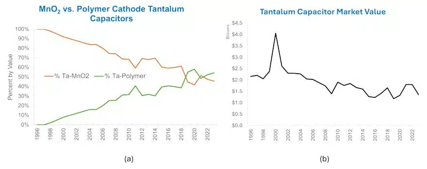
The Tantalum-Polymer capacitor market has grown, surpassing Tantalum-MnO2 capacitors around 2019. Tantalum-MnO2 capacitors are still used in cost-sensitive applications with low ESR, low DC leakage currents, and high temperature operation.
The conductive polymer cathode revolutionized the solid Tantalum capacitor, making it the preferred choice for many modern applications.
Tantalum Capacitor Industry Today and Future Directions
Over the past 40 years, tantalum capacitor manufacturers have engaged in significant M&A activities (Figure 1). AVX, through acquisitions in the late 1980s and the TESLA Lanškroun factory in the early 1990s, expanded its reach. Vishay acquired Sprague Electric in 1992 and later Mallory, Tansitor, KEMET Wet Tantalum, and Holystone Tantalum-Polymer. KEMET also acquired EPCOS, Arcotronics, and TOKIN from NEC. Panasonic acquired Sanyo, including POSCAP Tantalum-Polymer, providing a full line of Aluminum and Tantalum Polymer capacitors.
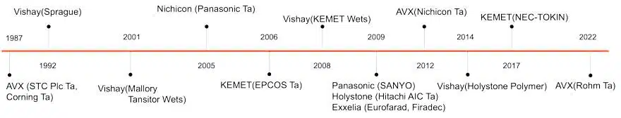
Today, four major manufacturers dominate the market: KEMET (owned by YAGEO Group), AVX (owned by Kyocera), Vishay, and Panasonic (polymer cathode types only). Smaller manufacturers include SEMCO (part of Samsung), Exxelia, Quantic-Evans, Matsuo, and Greatbatch. Several Chinese manufacturers primarily serve the Chinese market.
Tantalum capacitors compete with other technologies in various applications. Tantalum is limited to 125V (except for special wet tantalums). For smaller capacitances and case sizes, they compete with Class II MLCCs. For larger capacitances, they compete with Aluminum Electrolytics, especially polymer cathode Aluminum Electrolytics (SP-Cap and V-Chip types).
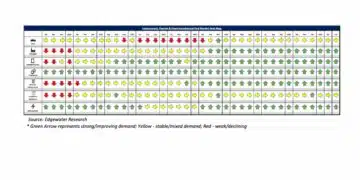
Tantalum capacitors are used in various applications, with Computer and Telecom/Cloud (over 50% market share) primarily using Tantalum-Polymer capacitors. Automotive was a large segment but lost favor due to MnO2 cathode types. Tantalum is making a comeback with Polymer cathode types. Military and medical applications still use them due to reliability. See Figure 9.

Future directions include advancing technology to meet evolving needs and position against other capacitor advances. Increasing capacitance in smaller packages has been a theme. Recently, as electronics have become thinner, this has also meant decreasing height. Tantalum capacitors below 1mm in height are available.
Tantalum capacitor surface mount packaging styles vary in active volume. The ‘gull-wing’ style, shown in the Figure 4., has a large inactive volume. For the 3.5×2.8×1.2mm package size, only 20% of the active volume is used. The face down or bottom terminal style has a higher active volume. Manufacturers are also moving to leadless packaging, eliminating the lead frame and direct connection to plated terminals, increasing the active volume to 2x that of the standard gull-wing style. See Fig. 10.

Tantalum-Polymer capacitors are increasingly used in long-life and harsh conditions applications, primarily in automotive and AI data centers. Automotive EV lifetimes exceed ICE, and OEMs require lifetimes over 100,000 hours. This has motivated the development of Tantalum-Polymer capacitors with 150°C temperature ratings, extending lifetimes under automotive duty cycles.
Tantalum-Polymer capacitors have advantages over Tantalum-MnO2 capacitors but suffer from ‘anomalous charging’. For an ideal capacitor, charging current is given by:

[4]
Anomalous charging occurs when the charging current exceeds the ideal current, often by several times. This is particularly problematic in circuit startup in power systems where high voltage ramping may exceed the power supply’s capacity. Factors like moisture level and temperature in the capacitor affect anomalous current. Space applications are particularly concerned due to extreme temperatures and a dry environment. Dr. Teverovsky at NASA studied this phenomenon. Manufacturers like AVX and KEMET have developed Tantalum-Polymer capacitors with lower anomalous currents.
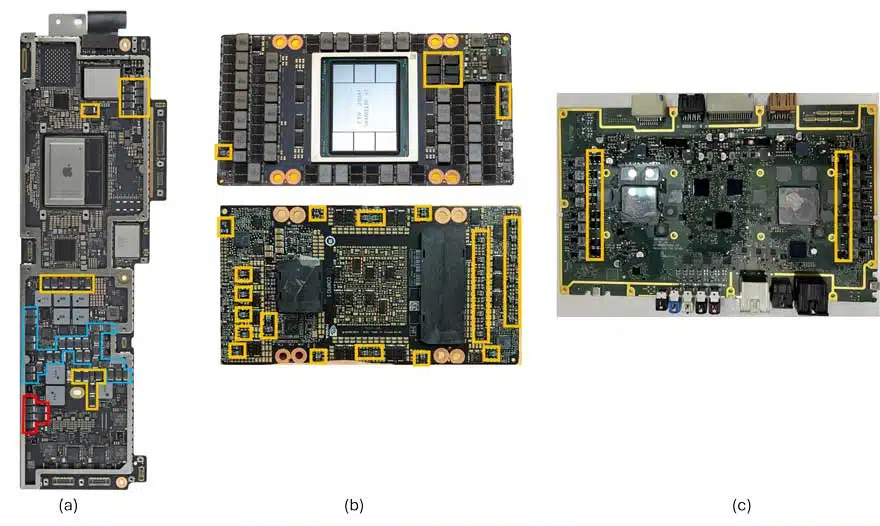
Despite challenges, Tantalum-Polymer capacitors find wide application in electronics. Figure 11. highlights their use in various applications, including:
- Notebook computer motherboards (Figure 11a): Early applications and volume drivers.
- Data centers (Figure 11b): Used in power delivery networks and as ‘last-gasp’ backup for enterprise solid state drives.
- Automotive advanced driver assist computers (Figure 11c): Based on the Nvidia Orin architecture.
The expanding applications bode well for continued development and commercial sales.
Read the more detailed tantalum capacitor history blogs at: Phil Lessner, Ph.D blog.
References
- P. Robinson, “Electrical Capacitors,” US Patent 3,066,247 (November 27, 1962).
- R.J. Millard, “Electrolytic Device”, US Patent 2,936,514 (May 17, 1960).
- H.E. Haring and R.L. Taylor, “Dry Electrolytic Device”, US Patent 3,166,693 (January 19, 1965).
- D. M. Smyth, G. A. Shirn, and T. B. Tripp, “Heat Treatment of Anodic Films on Tantalum: 1. Effects on the Dielectric Properties,” J. Electrochem. Soc., 110 (12), 1264 (1963). D.M. Smyth and T.B. Tripp, “Heat Treatment of Anodic Films on Tantalum: II. Temperature Dependence of Capacitance,” J. Electrochem. Soc., 110 (12), 1271 (1963). D. M. Smyth, G. A. Shirn, and T. B. Tripp, “Heat Treatment of Anodic Films on Tantalum: 1. The Conductivity Profile,” J. Electrochem. Soc., 111 (12), 1331 (1964). D. M. Smyth, G. A. Shirn, and T. B. Tripp, “Heat Treatment of Anodic Films on Tantalum: IV. Anodization in Phosphoric Acid Solutions,” J. Electrochem. Soc., 113 (2), 100 (1966). D. M. Smyth, “Heat Treatment of Anodic Films on Tantalum: V. The Thermal Redistribution of Incorporated Phosphorous,” J. Electrochem. Soc., 113 (12), 1371 (1966). D. M. Smyth, “Heat Treatment of Anodic Films on Tantalum: VI. The Effect of Chemical Thinning,” J. Electrochem. Soc., 114 (7), 723 (1967).
- G. Klein, “Oxidation State of Anodic Tantalum Oxide after Heat Treatment I. Galvanostatic Method as Applied after Heating in Vacuum,” J. Electrochem. Soc., 119(11), 1551 (1972).
- Y. Freeman, Tantalum and Niobium-Based Capacitors, page 54, 2nd Ed., Springer, 2022.
- Y. Pozdeev-Freeman, et al., “Critical Oxygen Content in Porous Anodes of Solid Tantalum Capacitors,” Journal of Materials Science: Materials in Electronics, 9, 309 (1998). Y. Pozdeev-Freeman, et al., “Effect of Dissolved Oxygen on Thermal Oxidation in Ta2O5/Ta Sandwiches,” Journal of Electronic Materials, 27, 1034 (1998). Y. Pozdeev-Freeman and A. Gladkikh, “Effect of Thermal Oxide on the Crystallization of the Anodic Ta2O5 Film,” Journal of Electronic Materials, 30, 931 (2001).
- Y. Pozdeev-Freeman, “Method for Doping Sintered Tantalum and Niobium Pellets with Nitrogen,” US Patent 6,410,083B1 (June 25, 2002). Y. Pozdeev-Freeman, “Sintered Tantalum and Niobium Capacitor Pellets Doped with Nitrogen, and Method of Making the Same,” US Patent 6,447,570B1 (September 10, 2002).
- Y. Freeman, Tantalum and Niobium-Based Capacitors, 2nd Ed., Springer, 2022.
- D. Vermilyea, “The Crystallization of Anodic Tantalum Oxide Films in the Presence of a Strong Electric Fields,” J. Electrochem. Soc., 102(5), 207 (1955). D. Vermilyea, “Nucleation of Crystalline Ta2O5 During Field Crystallization,” J. Electrochem. Soc., 104(9), 542 (1955).
- J.J. Randall Jr., W.J. Bernard, and R.L. Wilkinson, “A Radiotracer Study of the Composition and Properties of Anodic Oxide Films on Tantalum and Niobium,” Electrochimica Acta, 10, 183 (1965).
- J.D. Sloppy, “Anodization Mechanism and Properties of Bi-Layer Tantalum Oxide Formed in Phosphoric Acid,” PhD Dissertation, Pennsylvania State University (2009). J.D. Sloppy, et al., “Growth Laws of Bilayer Anodized Tantalum Oxide Films Formed in Phosphoric Acid,” J. Electrochem. Soc., 157(5), C157 (2010). J.D. Sloppy, et al., “Growth mechanism of anodic tantalum pentoxide formed in phosphoric acid,” Electrochimica Acta, 87, 82 (2013).
- J.T. Kinard and B. Melody, “Method of Anodizing a Metal Anode Prepared from Very Fine Metal Powder,” US Patent 6,162,345A (December 19, 2000).
- B. Melody, J.T. Kinard, and D. Wheeler, “Anodizing Electrolyte and its Use”, US Patent 5,716,511A (February 10, 1998).
- D.E Maguire, “Expressing Capacitor Reliability Accurately,” Electronic Industries, (December 1962). G.H. Didinger, Jr., “Tantalum Capacitor Accelerated Life Testing, Evaluation Engineering, (December 1964). H.W. Holland, “The Impact of Established Reliability Specification MIL-C-39003 on Solid Tantalum Capacitors,” Evaluation Engineering, 7(1) (Jan-Feb 1968).
- https://www.vishay.com/docs/40000/194d.pdf, Accessed on August 28, 2024.
- https://www.kyocera-avx.com/docs/techinfo/Tantalum-NiobiumCapacitors/smallesttacaps.pdf,Accessed on August 28, 2024.
- D. Zogbi, “Tantalum Capacitors: Global Market Update and Outlook 2024-2030,” ISBN# 0-929717-02-3, p. 3 (2024).
- J. Piper, “Electrolytic Capacitor with Separate Interconnected Anode Bodies,” US Patent 3,686,535 (August 22, 1972).
- I. Horacek, et al., “Improved ESR on MnO2 Tantalum Capacitors at Wide Voltage Range,” accessed at https://kyocera-avx.com/docs/techinfo/Tantalum-NiobiumCapacitors/impesr.pdf
- P. Winkel and D.G. de Groot, “Impedance of Dielectric Layers,” Philips Res. Reports, 13, 489 (1958). D.A. McLean, “The A-C Properties of Tantalum Solid Electrolytic Capacitors,” J. Electrochem. Soc., 108, 48 (1961). B. Goudswaard, “The Equivalent Series Resistance of Tantalum Solid Electrolytic Capacitors,” Electrochem. Tech., 6, 178 (1968).
- R. Hahn, et al., “Tantalum Capacitor Impregnation Process,” US Patent 5,622,746 (April 22, 1997).
- J. Prymak, “Spice Models of Capacitors,” KEMET Tech Topics, 4(5) (September 1994).
- H. Shirakawa, et al., “Synthesis of Electrically Conducting Organic Polymers: Halogen Derivatives of Polyacetylene (CH)x,” J. Chem. Soc., Chem. Commun., 578 (1977).
- Y. Kudoh, et al., “A Highly Thermostable Aluminum Solid Electrolytic Capacitor with an Electroconducting-Polymer Electrolyte,” in M. Aldissi, (ed.) Intrinsically Conducting Polymers: An Emerging Technology, Kluwer Academic Publishers, p. 191 (1993).
- T. Fukaumi, et al., “Polymer Tantalum Capacitor,” NEC Technical Journal, 46(12) (1993).
- F. Jonas, et al., “Solid Electrolytes, and Electrolyte Capacitors Containing Same,” US Patent 4,910,645A (March 20, 1990).
- K. Araki, et al., “Development of NEOCAPACITOR PSL Series,” NEC Technical Journal, 51(10) (1998).
- A. Elschner, et al., PEDOT Principles and Applications of an Intrinsically Conductive Polymer, Chapter 9, CRC Press (2011).
- Y. Qiu, R. Hahn, and K. Brenneman, “High Voltage Solid Electrolytic Capacitors Using Conductive Polymer Slurries,” US Patent 7,563,290B2 and US Patent 7,990,683B2 (2009 and 2011).
- J. Young and J. Qazi, “Polymer Tantalum Capacitors for Automotive Applications,” CARTS International (2014). J. Ye, et al., “Conductive Polymer Based Tantalum Capacitor for Automotive Applications,” T.I.C. 56th General Assembly (2015).
- https://www.kemet.com/en/us/capacitors/polymer/polymer-high-reliability.html , Accessed August 18, 2024.
- https://content.kemet.com/datasheets/KEM_T2090_T580-581.pdf, Accessed August 18, 2024.
- A. Chacko, et al., “High Temperature Tantalum Polymer Capacitors,” T.I.C. 60th General Assembly (2019).
- Y. Freeman, et al., “Anomalous Currents in Low Voltage Polymer Tantalum Capacitors,” ECS Journal of Solid State Science and Technology, 2(11), N197 (2013).
- A. Teverovsky, “Metrics for Anomalous Charging Currents in Polymer Tantalum Capacitors,” IEEE Electrical Insulation Conference (EIC), p. 1 (2023).
- J. Petržílek, et al., “Polymer Tantalum Capacitors with Suppressed Transient Current,” accessed at https://www.kyocera-avx.com/docs/techinfo/Tantalum-NiobiumCapacitors/Poly-Tant-Caps-Suppressed-Transient.pdf
- A. Chacko, et al., “Capacitor with Charge Time Reducing Additives and Work Function Modifiers,” US Patent 9,793,058B2 (October 17, 2017).