Passive Components Blog
No Result
View All Result
  • Home
  • NewsFilter
    • All
    • Aerospace & Defence
    • Antenna
    • Applications
    • Automotive
    • Capacitors
    • Circuit Protection Devices
    • electro-mechanical news
    • Filters
    • Fuses
    • Inductors
    • Industrial
    • Integrated Passives
    • inter-connect news
    • Market & Supply Chain
    • Market Insights
    • Medical
    • Modelling and Simulation
    • New Materials & Supply
    • New Technologies
    • Non-linear Passives
    • Oscillators
    • Passive Sensors News
    • Resistors
    • RF & Microwave
    • Telecommunication
    • Weekly Digest

    Bourns Release Automotive 4-Terminal Shunt Resistors

    Bourns Releases High Inductance Common Mode Choke

    Vishay Releases Automotive TO-220 Case 50W Thick Film Power Resistor

    High Energy Density Polymer Film Capacitors via Molecular and Interfacial Design

    Bourns Releases High Clearance and Creepage 1500VDC Power Transformer

    KYOCERA AVX Expands Stacked MLCC Capacitors Offering

    Murata and QuantumScape Joint Development for Solid Batteries Ceramic Separators

    YAGEO Unveils Compact 3.6kW LLC Transformer for OBC EV Charging

    Over-Voltage Protection Clippers, Clampers, Snubbers, DC Restorers

    Trending Tags

    • Ripple Current
    • RF
    • Leakage Current
    • Tantalum vs Ceramic
    • Snubber
    • Low ESR
    • Feedthrough
    • Derating
    • Dielectric Constant
    • New Products
    • Market Reports
  • VideoFilter
    • All
    • Antenna videos
    • Capacitor videos
    • Circuit Protection Video
    • Filter videos
    • Fuse videos
    • Inductor videos
    • Inter-Connect Video
    • Non-linear passives videos
    • Oscillator videos
    • Passive sensors videos
    • Resistor videos

    Connector PCB Design Challenges

    Efficient Power Converters: Duty Cycle vs Conduction Losses

    Ripple Steering in Coupled Inductors: SEPIC Case

    SEPIC Converter with Coupled and Uncoupled Inductors

    Coupled Inductors in SEPIC versus Flyback Converters

    Non-Linear MLCC Class II Capacitor Measurements Challenges

    Percolation Phenomenon and Reliability of Molded Power Inductors in DC/DC converters

    Root Causes and Effects of DC Bias and AC in Ceramic Capacitors

    How to Calculate the Output Capacitor for a Switching Power Supply

    Trending Tags

    • Capacitors explained
    • Inductors explained
    • Resistors explained
    • Filters explained
    • Application Video Guidelines
    • EMC
    • New Products
    • Ripple Current
    • Simulation
    • Tantalum vs Ceramic
  • Knowledge Blog
  • Suppliers
    • Who is Who
  • PCNS
    • PCNS 2025
    • PCNS 2023
    • PCNS 2021
    • PCNS 2019
    • PCNS 2017
  • Events
No Result
View All Result
Passive Components Blog
No Result
View All Result

PTC Thermistors Applications

29.2.2024
Reading Time: 6 mins read
A A

One of the properties of PTC thermistors is that when an excessively large current flows, they generate heat by themselves and become highly resistive. With this property, they are used as overcurrent protection devices.

This article describes applications for the following purposes.

RelatedPosts

Overvoltage Protection Selection Guidelines: TVS Diodes, MOVs, and ESD MOV Varistors

ESD Electrostatic Discharge Protection by TVS Diode

Chip Varistors Applications for ESD Countermeasures

  • For inrush current limiting
  • For overcurrent protection
  • For telecom

Advantages of PTC thermistors

PTC thermistors are temperature-dependent resistors based on special semiconductor ceramics with a high positive temperature coefficient (PTC). They exhibit relatively low resistance values at room temperature. When a current flows through a PTC the heat generated raises the temperature of the PTC. Once a certain temperature (Curie temperature) is exceeded, the resistance of a PTC rises significantly.

This effect can be used to protect circuits or devices against overcurrents. In this case, the overcurrent brings the PTC to a high temperature and the resulting high resistance then limits the overcurrent. When the cause for malfunction is eliminated the PTC will cool down and act again as a resettable fuse. With this property, PC thermistors are used as overcurrent protection devices. The following exemplary applications describe how PTC thermistors can be used for overcurrent protection.

Applications of PTC thermistors for inrush current limiting


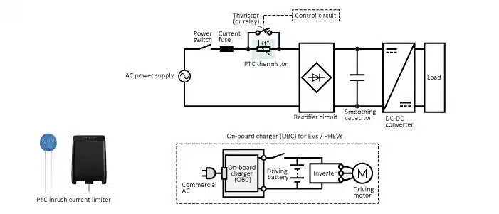
Application: Inrush current limiting for on-board chargers (OBC)

Switch-mode power supplies (SMPS), which are small and lightweight and offer high-performance, are often used as power supplies of electronic devices. When an SMPS is switched on (i.e. when charging of a smoothing capacitor starts), an inrush current with a high peak flows through the device. This inrush current may negatively impact the service life of the smoothing capacitor, damage contacts of the power switch, or destroy a rectifier diode. Therefore, it is necessary to limit the inrush current to the SMPS.The circuit diagram below shows an example of an inrush current limiter (ICL) circuit, in which a PTC thermistor and a thyristor (or a mechanical relay) are used in combination.When the power switch is closed and the charging process starts, the uncharged capacitor is like a short circuit and therefore draws a very high inrush current. Because the thyristor is in high ohmic state (a mechanical relay would be in open state) at that time, the PTC which is connected in series to the smoothing capacitor limits the inrush current (charging current of the capacitor) to a desired lower level. Once the capacitor is charged, the thyristor short-circuits the PTC and the electrical load is applied.

In some cases, the thyristor (or the mechanical relay) may malfunction and not short-circuit the PTC. When this happens, the load is applied to the circuit and the high operating current heats up the PTC. The PTC then enters a high ohmic state, thus reducing the malfunction current to a lower level that is not dangerous. PTC thermistors can withstand such loading without suffering any damage.

If a fixed resistor is used for inrush current limiting, as was common in the past, the high operating current can thermally overstress the resistor and even destroy the resistor or cause a fire to break out.

Figure 1 Inrush current limiting in a switch-mode power supply

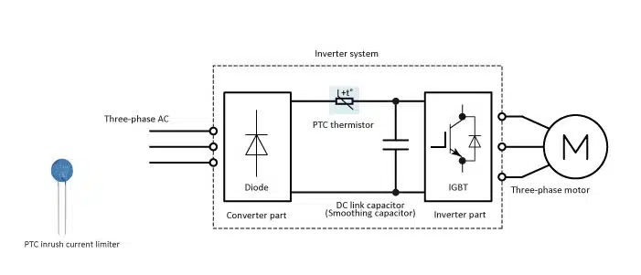
Application: Inrush current limiting for industrial inverters

Induction motors are often used for fans, pumps, air conditioners and other equipment in factories. An induction motor is simple in structure, is robust, and its speed depends on the frequency of the power supply. Inverters are used to control the speed of induction motors. Such variable frequency drives (VFDs) increase the efficiency of the motor and therefore reduce power consumption.An inverter system consists of a converter part and an inverter part. A DC link capacitor (smoothing capacitor) is placed after the converter part. When the system is powered on, the DC link capacitor is charged with an inrush current whose peak is several times than the steady current needed to charge the capacitor. This inrush current can have a harmful effect on the service life of the capacitor or destroy semiconductor devices exposed to the current.

A very good way to limit the inrush current is to use an inrush current limiter (ICL), in which a PTC thermistor and a thyristor (or relay) are used in combination with each other.

The function of the PTC ICL is the same as described for the onboard charger application. Again, the PTC has self-protecting properties (increased resistance in case of a circuit malfunction)

Figure 2 Inrush current limiting in an industrial inverter

Applications of PTC thermistors for overcurrent protection

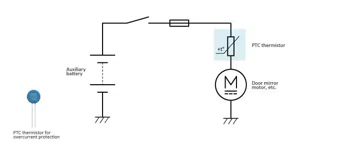
Application: Overcurrent protection for on-board DC motors

When a motor is overloaded or rotation of a motor is stopped (locked), an overcurrent flows through the motor. This can result in thermal overstress to the coil. PTC thermistors can effectively protect motors from such overcurrent.For example, if the side mirror of a car is blocked by an object, the motor will lock when an attempt is made to set the mirror or retract it. This will result in an overcurrent through the motor winding. In order to protect against thermal overstress a PTC thermistor is used. The high current causes the PTC to heat up. The resistance of the PTC then increases substantially, which in turn reduces the high current to levels that do not overstress the system. Such overcurrent protection thermistors are also used for the motors driving power locks and power seats, for example.

Figure 3 Example of protecting an on-board DC motor

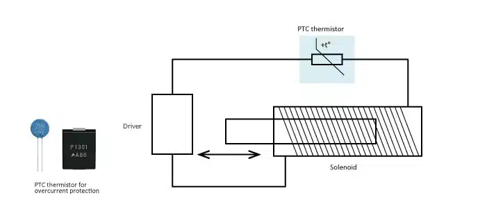
Application: Overcurrent protection for solenoids

Solenoids which make armatures move by magnetic force of their coil are simple and convenient actuators used in office automation equipment such as printers as well as electric locks. Solenoids are available as direct acting types, rotary types, and other types. If a solenoid coil is overloaded an overcurrent flows through the coil, potentially causing excessive thermal stress. Solenoid coils can be protected easily by connecting a PTC thermistor which heats up in the case of overcurrent and reduces the current.

Figure 4 Inrush current prevention in a solenoid

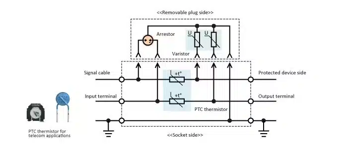
Application: Overcurrent protection in a surge protective device (SPD) used for security systems

PTC thermistors for telecom applications are also used for various security systems in factories and office buildings. For example, surge protective devices (SPD) are installed at important locations in these systems because signal cables used for fire alarm systems, surveillance camera systems, and other network systems that connect multiple sites can be damaged by lightning surges.

The diagram below shows an example of a protection circuit that uses a replaceable plug-in SPD. The plug side includes an arrestor and a varistor for overvoltage protection. The socket side includes a PTC thermistor for overcurrent protection.


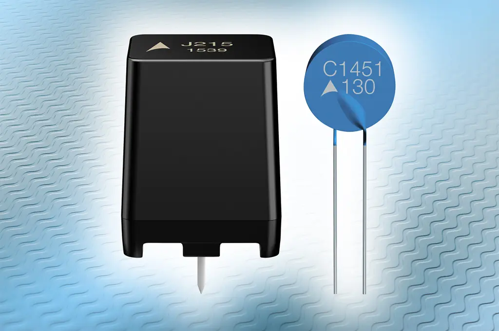
TDK offers a comprehensive lineup of PTC thermistors for telecom applications. Telecom pair protectors (TPP), each of which incorporates two PTC thermistors packaged in a plastic case, are often used for SPDs.


The function of the PTC is very similar to that described in the previous section.

Figure 5 Example of a protection circuit for plug-in surge protection device (SPD)

Related

Source: TDK

Recent Posts

Bourns Release Automotive 4-Terminal Shunt Resistors

17.10.2025
5

Bourns Releases High Inductance Common Mode Choke

16.10.2025
11

Vishay Releases Automotive TO-220 Case 50W Thick Film Power Resistor

16.10.2025
6

High Energy Density Polymer Film Capacitors via Molecular and Interfacial Design

15.10.2025
14

Bourns Releases High Clearance and Creepage 1500VDC Power Transformer

15.10.2025
14

KYOCERA AVX Expands Stacked MLCC Capacitors Offering

14.10.2025
27

YAGEO Unveils Compact 3.6kW LLC Transformer for OBC EV Charging

13.10.2025
122

Over-Voltage Protection Clippers, Clampers, Snubbers, DC Restorers

13.10.2025
24

KYOCERA Releases Shielded Board-to-Board Connectors for Reliable EMI Protection

13.10.2025
24

Silicon Capacitors Market: Shaping the Foundation for Next-Gen Miniaturization Electronics

10.10.2025
53

Upcoming Events

Oct 20
October 20 - October 23

Digital WE Days 2025 – Virtual Conference

Oct 21
October 21 @ 12:00 - October 23 @ 14:15 EDT

Space and Military Standards for Hybrids and RF Microwave Modules

Oct 28
8:00 - 15:00 CET

Power Up Your Design: SN6507 and the Ready-to-Use Development Kit

View Calendar

Popular Posts

  • Buck Converter Design and Calculation

    0 shares
    Share 0 Tweet 0
  • Boost Converter Design and Calculation

    0 shares
    Share 0 Tweet 0
  • Flyback Converter Design and Calculation

    0 shares
    Share 0 Tweet 0
  • LLC Resonant Converter Design and Calculation

    0 shares
    Share 0 Tweet 0
  • Ripple Current and its Effects on the Performance of Capacitors

    3 shares
    Share 3 Tweet 0
  • What is a Dielectric Constant and DF of Plastic Materials?

    4 shares
    Share 4 Tweet 0
  • SEPIC Converter Design and Calculation

    0 shares
    Share 0 Tweet 0
  • MLCC and Ceramic Capacitors

    0 shares
    Share 0 Tweet 0
  • Dual Active Bridge (DAB) Topology Explained

    0 shares
    Share 0 Tweet 0
  • Flying Capacitors

    0 shares
    Share 0 Tweet 0

Newsletter Subscription


Passive Components Blog

© EPCI - Leading Passive Components Educational and Information Site

  • Home
  • Privacy Policy
  • EPCI Membership & Advertisement
  • About

No Result
View All Result
  • Home
  • Knowledge Blog
  • PCNS

© EPCI - Leading Passive Components Educational and Information Site

This website uses cookies. By continuing to use this website you are giving consent to cookies being used. Visit our Privacy and Cookie Policy.
Go to mobile version