Passive Components Blog
No Result
View All Result
  • Home
  • News
    • All
    • Aerospace & Defence
    • Antenna
    • Applications
    • Automotive
    • Capacitors
    • Circuit Protection Devices
    • electro-mechanical news
    • Filters
    • Fuses
    • Inductors
    • Industrial
    • Integrated Passives
    • inter-connect news
    • Market & Supply Chain
    • Market Insights
    • Medical
    • Modelling and Simulation
    • New Materials & Supply
    • New Technologies
    • Non-linear Passives
    • Optoelectronics and Isolation
    • Oscillators
    • Passive Sensors News
    • Resistors
    • RF & Microwave
    • Telecommunication
    • Weekly Digest
    Sep 2026 electronics market heat map

    September 2026 Interconnect, Passives and Electromechanical Components Market Insights

    Würth Elektronik electronica 2026 presentation featuring electronic components, PCB technologies and high-current PowerBusbar connection solutions.

    Würth Elektronik Previews Components, PCBs and Power Solutions at electronica 2026

    Two Murata LLD three-terminal MLCCs beside a metal ruler, showing beige ceramic bodies and silver-coloured terminals.

    Murata Begins Production of 0201 Three-Terminal Low-ESL MLCCs for IC Decoupling

    Bourns SRP201210V low-profile shielded SMD power inductors for compact portable electronics

    Bourns Releases Compact Shielded Power Inductors

    LeanBOM Working Conditions search showing DC-bias capacitance curves for capacitor candidates at 88 degrees Celsius

    LeanBOM Expands Capacitor Catalogue and Comparison Tools

    Vishay Sfernice D2TO35S TO-263 top-side cooled thick-film power resistor with metal heatsink interface

    Vishay Unveils Top-Side Cooled 35 W Power Resistor

    TDK and TAIYO YUDEN business alliance announcement for advanced MLCCs and inductors supporting AI infrastructure.

    TDK and TAIYO YUDEN Explore Alliance for MLCCs and Inductors

    Antiferroelectric hafnia crystal structure showing alternating polar layers and field-aligned polar state, University of Nebraska–Lincoln

    Antiferroelectric Hafnia at the 2D Limit

    Bourns UALH Series aluminum housed high-power wirewound resistor in a thin rectangular metal enclosure

    Bourns Wirewound Resistors Target 100 W Industrial Designs

    Trending Tags

    • Ripple Current
    • RF
    • Leakage Current
    • Tantalum vs Ceramic
    • Snubber
    • Low ESR
    • Feedthrough
    • Derating
    • Dielectric Constant
    • New Products
    • Market Reports
  • Knowledge Blog
  • Dossiers
    • AI Hardware Dossier
    • Automotive Dossier
    • Industrial Robotics Dossier
    • Power Converter Dossier
    • Capacitor Dossier
    • Resistor Dossier
    • Inductor Dossier
    • Circuit Protection Dossier
  • Suppliers
    • Who is Who
  • PCNS
    • PCNS 2025
    • PCNS 2023
    • PCNS 2021
    • PCNS 2019
    • PCNS 2017
  • Events
  • Home
  • News
    • All
    • Aerospace & Defence
    • Antenna
    • Applications
    • Automotive
    • Capacitors
    • Circuit Protection Devices
    • electro-mechanical news
    • Filters
    • Fuses
    • Inductors
    • Industrial
    • Integrated Passives
    • inter-connect news
    • Market & Supply Chain
    • Market Insights
    • Medical
    • Modelling and Simulation
    • New Materials & Supply
    • New Technologies
    • Non-linear Passives
    • Optoelectronics and Isolation
    • Oscillators
    • Passive Sensors News
    • Resistors
    • RF & Microwave
    • Telecommunication
    • Weekly Digest
    Sep 2026 electronics market heat map

    September 2026 Interconnect, Passives and Electromechanical Components Market Insights

    Würth Elektronik electronica 2026 presentation featuring electronic components, PCB technologies and high-current PowerBusbar connection solutions.

    Würth Elektronik Previews Components, PCBs and Power Solutions at electronica 2026

    Two Murata LLD three-terminal MLCCs beside a metal ruler, showing beige ceramic bodies and silver-coloured terminals.

    Murata Begins Production of 0201 Three-Terminal Low-ESL MLCCs for IC Decoupling

    Bourns SRP201210V low-profile shielded SMD power inductors for compact portable electronics

    Bourns Releases Compact Shielded Power Inductors

    LeanBOM Working Conditions search showing DC-bias capacitance curves for capacitor candidates at 88 degrees Celsius

    LeanBOM Expands Capacitor Catalogue and Comparison Tools

    Vishay Sfernice D2TO35S TO-263 top-side cooled thick-film power resistor with metal heatsink interface

    Vishay Unveils Top-Side Cooled 35 W Power Resistor

    TDK and TAIYO YUDEN business alliance announcement for advanced MLCCs and inductors supporting AI infrastructure.

    TDK and TAIYO YUDEN Explore Alliance for MLCCs and Inductors

    Antiferroelectric hafnia crystal structure showing alternating polar layers and field-aligned polar state, University of Nebraska–Lincoln

    Antiferroelectric Hafnia at the 2D Limit

    Bourns UALH Series aluminum housed high-power wirewound resistor in a thin rectangular metal enclosure

    Bourns Wirewound Resistors Target 100 W Industrial Designs

    Trending Tags

    • Ripple Current
    • RF
    • Leakage Current
    • Tantalum vs Ceramic
    • Snubber
    • Low ESR
    • Feedthrough
    • Derating
    • Dielectric Constant
    • New Products
    • Market Reports
  • Knowledge Blog
  • Dossiers
    • AI Hardware Dossier
    • Automotive Dossier
    • Industrial Robotics Dossier
    • Power Converter Dossier
    • Capacitor Dossier
    • Resistor Dossier
    • Inductor Dossier
    • Circuit Protection Dossier
  • Suppliers
    • Who is Who
  • PCNS
    • PCNS 2025
    • PCNS 2023
    • PCNS 2021
    • PCNS 2019
    • PCNS 2017
  • Events
No Result
View All Result
Passive Components Blog
No Result
View All Result

Test Explanations: Connector Resistance

14.9.2021
Reading Time: 5 mins read
A A

For convenience a review of the components of connector resistance, first presented in 1.3.3 The Electrical Interface: Contact Resistance, will be provided. Figure 2.98 shows a cross section of a connector with the three major connector resistance components highlighted. The overall resistance of a connector (RO) will be given by the sum of the permanent connection (RPC), bulk (RB) and contact interface (RC) resistances.
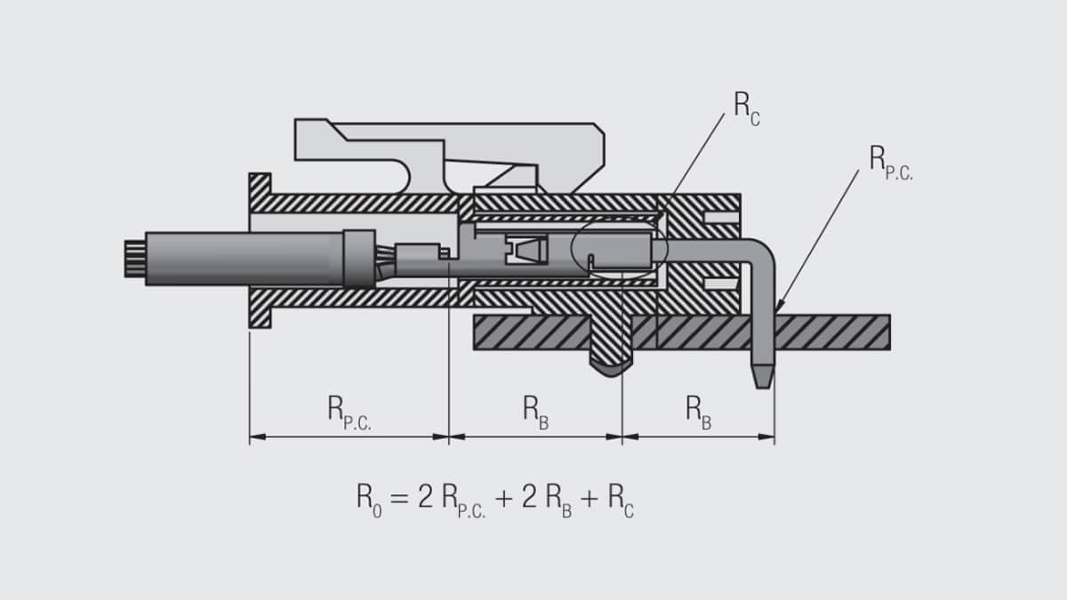
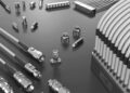
Fig. 2.111: Connector contact resistance

Permanent Connection Resistance
The dominant permanent connection resistances are those of crimped, insulation displacement, compliant pin and soldered connections. Figure 2.111 illustrates crimped and compliant pin permanent connections. The resistance of permanent connections is generally small, fractions of a milliohm, and stable. The low magnitude of the resistance is due to the large contact areas typical of permanent connections. The stability is provided, for mechanical connections, by the large deformations and high forces used during the connection process. For soldered connections the solder volumes also typically provide large and stable contact areas. A typical connector will have two permanent connection resistances, one on the receptacle and one on the plug.

RelatedPosts

Polymer Materials and Processing

What is RF Connector

Connector Materials and Processes

Bulk Resistance
The bulk resistance of a connector is due to the material and geometry of the contact springs. The most important material parameter is the electrical resistivity of the contact spring material. A simple equation illustrates the importance of contact spring geometry. The resistance of a conductor is given by:

where R is the overall resistance of the conductor, ρ is the electrical resistivity of the conductor material, and L and A are the length and cross sectional area of the conductor respectively. A typical connector will have two bulk resistances, that of the receptacle and plug contacts. The bulk resistance contributions generally account for the majority of the connector overall resistance in typical connectors.

Contact Interface Resistance
The contact interface resistance, RC , is that due to the metallic contact areas created when the receptacle and plug contacts come together during mating. The important parameters determining RC are:

where RC is the contact interface resistance, ρ is the electrical resistivity of the contact spring material, H is the hardness of the contact surface materials and FN is the contact normal force. While multiple beam contacts may have more than one contact interface, RC is generally taken as a single value. The magnitude of RC is between that of permanent and bulk resistances, being closer to permanent connections in signal connectors and closer to bulk resistances in power contacts.

The magnitude of connector overall resistances falls in the range of fractional milliohms (power applications) to a few tens of milliohms (signal applications).

Contact Resistance Measurement Methods
There are two commonly used electrical resistance measurements: Low Level Contact Resistance (LLCR) and Contact Resistance at Rated Current (CRRC). These methods differ primarily in the means and magnitudes of the voltages and currents applied during the measurement.

LLCR measurements are voltage controlled with an open circuit voltage of the order of tens of millivolts. Some specifications require 20 mV maximum, while others allow 50 mV. These measurement voltages are intended to be so low that they are insufficient to cause dielectric breakdown of any films which may be on the surface of the contacts at the contact interface. In other words such resistance measurements indicate metal-to-metal contact interfaces. LLCR measurements are sometimes referred to as “dry circuit” measurements. This terminology dates back to days when voltage spikes, “wetting voltages” were applied to break down surface films, the low millivolt open circuit voltage, therefore, was identified as “dry circuit” voltage. The test current is typically 100 milliamperes though lower currents are sometimes specified.

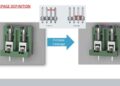
LLCR measurements are generally made using what is called a “4-wire” or Kelvin measurement circuit. A basic 4-wire circuit is shown in Figure 2.112. Note that two wires, one source and one sense wire feed into the top and the bottom of the sample.
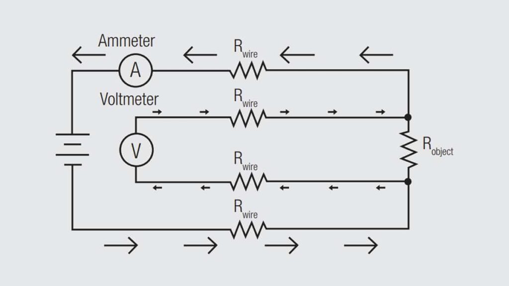
Fig. 2.112: Schematic of 4-wire (Kelvin) resistance measurement circuit

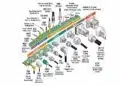
Figure 2.113 shows this circuit implemented in a Kelvin Clip to facilitate resistance measurements. The respective A and V tips are mechanically coupled to clip to the sample, but electrically insulated from one another.
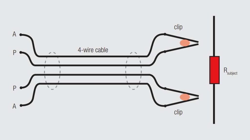
Fig. 2.113: Kelvin clip implementation of the Kelvin circuit

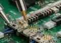
Kelvin clips are generally used to measure the resistance of individual contacts as shown in Figure 2.114. The same basic schematic, of course, can be expanded to enable the measurement of multiple contact positions in a housing. When board mounted connectors are being measured, attention must be paid to ensure that the requirements of the Kelvin schematic are realized on the PCB.
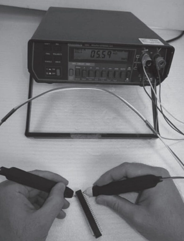
Fig. 2.114: Contact resistance measurement using Kelvin clips

CRRC resistance measurements use a similar (4-wire) circuit, but the current is controlled to the rated current of the connector, several to tens of amperes. The millivolt drop across the contact is then measured and the resistance calculated from Ohm’s law. The driving voltage to realize the rated current will generally exceed the few tens of millivolts allowed for LLCR measurements. CRRC should not be measured until thermal stability has been achieved, for example until two successive contact temperature measurements after the specified time interval show the same temperature.

In cases where both resistance measurements may be required, such as power connectors, the following measurement sequence should be used: CRRC, LLCR, Conditioning-Exposure, LLCR, CRRC. CRRC precedes LLCR initially because the LLCR measurement provides the base reference for evaluating resistance. After the required conditioning/exposure sequences have been run LLCR is done first because the higher applied voltages used in CRRC measurements could disrupt any surface films which have formed during the exposures negating the effect of the exposures.

While details of attaching test probes to the sample connectors are application dependent it is always good practice to place the probes as close to the sources of resistance as possible to minimize any bulk resistance contributions of the input leads to the measurement. Special test boards are often necessary to test printed wiring board connectors to accomplish this end.

Related

Source: Wurth elektronik

Recent Posts

Circular Connectors Coding

26.11.2025
274

Connector PCB Design Challenges

3.10.2025
140

Non-Magnetic Interconnects

23.4.2025
71

10 Tips for Ensuring Reliability of Discrete Wire Assemblies

20.2.2025
100

Polymer Materials and Processing

11.8.2025
268

Basic PCB Technology Overview

1.7.2025
65

What is RF Connector

17.12.2024
99

Creepage and Clearance of Connector

25.7.2025
135

RF Connector Types: How To Choose the Right One

24.4.2026
1.1k

Upcoming Events

Oct 14
17:00 - 18:00 CEST

Live Demo! Discover KYOCERA AVX Antenna Integrator Studio (AIS)

Oct 19
15:00 - 16:00 CEST

ESCC-qualified Pt Temperature Sensors for Space Applications

Oct 27
16:00 - 17:00 CET

Power Inductor technologies

View Calendar

Popular Posts

  • Buck Converter Design and Calculation

    0 shares
    Share 0 Tweet 0
  • Boost Converter Design and Calculation

    0 shares
    Share 0 Tweet 0
  • LLC Resonant Converter Design and Calculation

    0 shares
    Share 0 Tweet 0
  • Flyback Converter Design and Calculation

    0 shares
    Share 0 Tweet 0
  • Capacitor Charging and Discharging

    0 shares
    Share 0 Tweet 0
  • Resistor Symbols

    0 shares
    Share 0 Tweet 0
  • Thermistors Basics, NTC and PTC Thermistors

    0 shares
    Share 0 Tweet 0
  • Audio Capacitors: Choosing Capacitors for Crossover Circuits

    0 shares
    Share 0 Tweet 0
  • Capacitor Symbols

    0 shares
    Share 0 Tweet 0
  • MLCC and Ceramic Capacitors

    0 shares
    Share 0 Tweet 0

Newsletter Subscription


Passive Components Blog

© 2015–2026
All rights reserved

  • Home
  • Privacy Policy
  • EPCI Membership & Advertisement
  • About

No Result
View All Result
  • Home
  • Knowledge Blog
  • Dossiers
  • PCNS

© 2015–2026
All rights reserved