Passive Components Blog
No Result
View All Result
  • Home
  • NewsFilter
    • All
    • Aerospace & Defence
    • Antenna
    • Applications
    • Automotive
    • Capacitors
    • Circuit Protection Devices
    • electro-mechanical news
    • Filters
    • Fuses
    • Inductors
    • Industrial
    • Integrated Passives
    • inter-connect news
    • Market & Supply Chain
    • Market Insights
    • Medical
    • Modelling and Simulation
    • New Materials & Supply
    • New Technologies
    • Non-linear Passives
    • Oscillators
    • Passive Sensors News
    • Resistors
    • RF & Microwave
    • Telecommunication
    • Weekly Digest

    DigiKey Offers Zephyr Operating System Workshop and Training Videos

    Exxelia to Present Smart Integrated Magnetics and MML Film Capacitors at SIAE25 

    What Track Width To Use When Routing PCB

    YAGEO Unveils PulseChip LAN Transformer

    Bourns Releases Automotive Impedance Matching Transformer

    Stackpole Offers Affordable Current Sense Chip Resistors

    Knowles Extends Range and Performance of C0G MLCC Capacitors

    May 2025 ECST Component Results Show Moderating Decline in Sales Sentiment

    Panasonic Releases New Aluminum Hybrid Capacitors with High Ripple Current in Compact Size

    Trending Tags

    • Ripple Current
    • RF
    • Leakage Current
    • Tantalum vs Ceramic
    • Snubber
    • Low ESR
    • Feedthrough
    • Derating
    • Dielectric Constant
    • New Products
    • Market Reports
  • VideoFilter
    • All
    • Antenna videos
    • Capacitor videos
    • Circuit Protection Video
    • Filter videos
    • Fuse videos
    • Inductor videos
    • Inter-Connect Video
    • Non-linear passives videos
    • Oscillator videos
    • Passive sensors videos
    • Resistor videos

    Coupled Inductors Circuit Model and Examples of its Applications

    Inductor Resonances and its Impact to EMI

    Highly Reliable Flex Rigid PCBs, Würth Elektronik Webinar

    Causes of Oscillations in Flyback Converters

    How to design a 60W Flyback Transformer

    Modeling and Simulation of Leakage Inductance

    Power Inductor Considerations for AI High Power Computing – Vishay Video

    Coupled Inductors in Multiphase Boost Converters

    VPG Demonstrates Precision Resistor in Cryogenic Conditions

    Trending Tags

    • Capacitors explained
    • Inductors explained
    • Resistors explained
    • Filters explained
    • Application Video Guidelines
    • EMC
    • New Products
    • Ripple Current
    • Simulation
    • Tantalum vs Ceramic
  • Knowledge Blog
  • Suppliers
    • Who is Who
  • Events
No Result
View All Result
Passive Components Blog
No Result
View All Result

Test Explanations: Vibration

14.9.2021
Reading Time: 3 mins read
A A

Vibration parameters are arguably the most problematic of the conditioning/exposure testing parameters. The most significant issue is that the vibration conditions in the field are unknown except for the recognition that they are application dependent and highly variable. Thus vibration testing is standardized to allow comparative rather than performance evaluations.

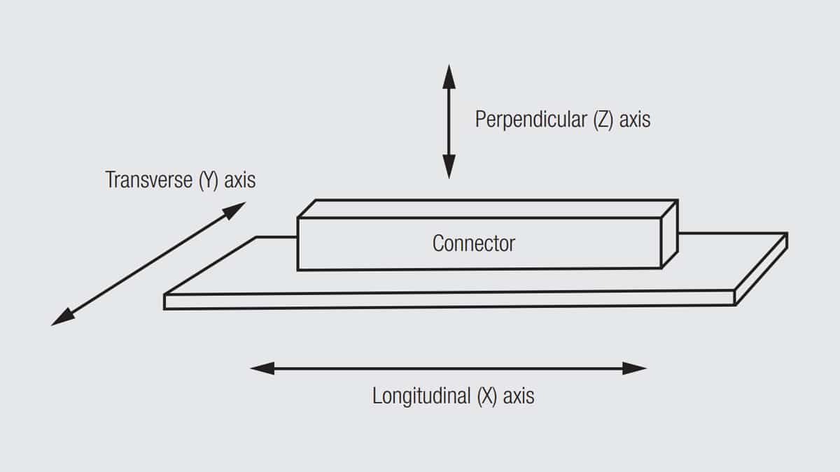
Vibration testing is performed in three axes as illustrated in Figure 2.118.

RelatedPosts

Polymer Materials and Processing

What is RF Connector

Connector Materials and Processes

Fig. 2.118: Vibration testing axis definition

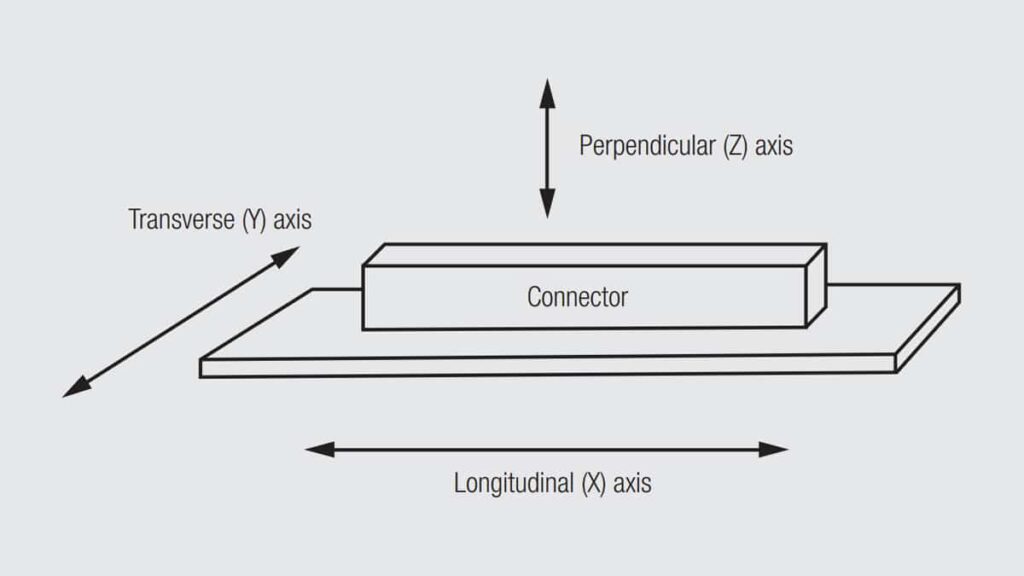
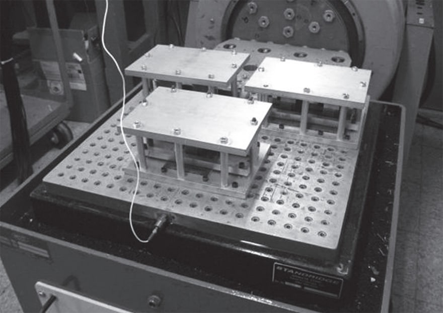
In the configuration shown in Figure 2.118, the Y and Z axes are the most significant. The Y axis is sensitive to rocking motions of the connector and, therefore, fretting motions and degradation, and the height of the connector can result in amplification of the rocking forces. The Z axis is the mating direction of the connector, and, therefore, is also susceptible to fretting degradation. Clearly how the connector is fixtured, and the orientation of the fixtured connection on the vibration table can have a significant influence on the connector performance in the test. A typical vibration table for fixturing of samples is shown in Figure 2.119.

Fig. 2.119: Typical vibration table (Photo courtesy T. Peel, Contech Research)

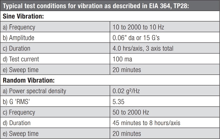
The two major vibration methodologies are sine and random vibration. Sine vibration sweeps through the selected frequency levels at a selected amplitude and for a selected duration. Random vibration, as the name implies, varies the frequencies and amplitudes of vibration within the selected frequency spectrum. While sine vibration is the most commonly specified method, the random vibration is more representative of field conditions. Table 2.8 shows typical vibration testing.

Tab. 2.8: Typical vibration parameters

Definition of a vibration environment involves consideration of at least the following factors: severity levels (amplitude and frequency), duration (time or cycles per axis), attributes to be monitored (resistance, discontinuities) and fixturing. The fixturing decisions must take a systems approach to look for factors that could amplify the effects of vibrational forces on the connector. For example, in an edge card connector the length of the board above the connector can have a significant effect on the vibrational impact on the Y axis.

LLCR is a commonly used measurement for vibration testing. It is used primarily for assessment of fretting degradation and can be done continuously or periodically depending on the data desired. Sophisticated data gathering techniques may be required for this purpose.

In addition to assessment of mechanical stability, vibration is also used to determine whether electrical discontinuities may occur during vibration. There are two levels of discontinuity monitoring. One microsecond discontinuity monitoring has been the most commonly used approach. Recently shorter discontinuities have become of interest and discontinuities in the range from 50 nanoseconds to 2 nanoseconds have been monitored with increasingly sophisticated measurement and fixturing requirements. Discussion of these methods are outside the scope of this chapter.

Related

Source: Wurth elektronik

Recent Posts

Non-Magnetic Interconnects

23.4.2025
20

10 Tips for Ensuring Reliability of Discrete Wire Assemblies

20.2.2025
51

Polymer Materials and Processing

31.1.2025
36

Basic PCB Technology Overview

17.12.2024
15

What is RF Connector

17.12.2024
7

Creepage and Clearance of Connector

16.10.2023
13

Microwave Multi Line Connectors Mounting and Handling Precautions

17.12.2024
2

BASIC PCB Design Rules – Layout

17.12.2024
23

MEMR RF Relay for Space Compact Redundancy Ring

17.12.2024
2

Connector Temperature Rise and Derating

13.1.2023
15

Upcoming Events

Jun 24
17:00 - 18:00 CEST

Ultra-Compact and Efficient Switched-Capacitor Power Converters

View Calendar

Popular Posts

  • Buck Converter Design and Calculation

    0 shares
    Share 0 Tweet 0
  • Boost Converter Design and Calculation

    0 shares
    Share 0 Tweet 0
  • Flyback Converter Design and Calculation

    0 shares
    Share 0 Tweet 0
  • What is a Dielectric Constant and DF of Plastic Materials?

    4 shares
    Share 4 Tweet 0
  • LLC Resonant Converter Design and Calculation

    0 shares
    Share 0 Tweet 0
  • Ripple Current and its Effects on the Performance of Capacitors

    3 shares
    Share 3 Tweet 0
  • Dual Active Bridge (DAB) Topology Explained

    0 shares
    Share 0 Tweet 0
  • SEPIC Converter Design and Calculation

    0 shares
    Share 0 Tweet 0
  • Flying Capacitors Explained

    0 shares
    Share 0 Tweet 0
  • How to Design an Inductor

    0 shares
    Share 0 Tweet 0

Newsletter Subscription


Passive Components Blog

© EPCI - Leading Passive Components Educational and Information Site

  • Home
  • Privacy Policy
  • EPCI Membership & Advertisement
  • About

No Result
View All Result
  • Home
  • Knowledge Blog
  • Premium Suppliers

© EPCI - Leading Passive Components Educational and Information Site

This website uses cookies. By continuing to use this website you are giving consent to cookies being used. Visit our Privacy and Cookie Policy.
Go to mobile version