In this article Frenetic power electronics engineer Sotiris Zorbas, MSc shares his personal experience with transformer testing and what he called “Lab traps” focusing in particular on the importance of parasitic inductors/capacitance in the secondary side of transformers.
60W Flyback Transformer Case Study
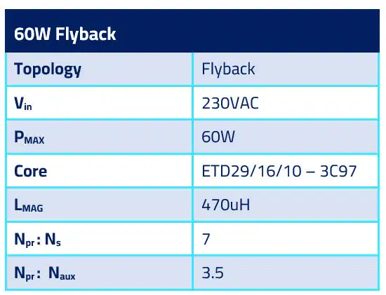
I used a flyback PSU capable of delivering 60W as an transformer test case study.
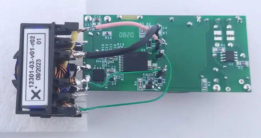
Because the board transformer had a different pinout, I used some round 0.7mm solid wires to extend the pins of my sample.
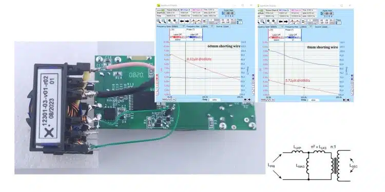
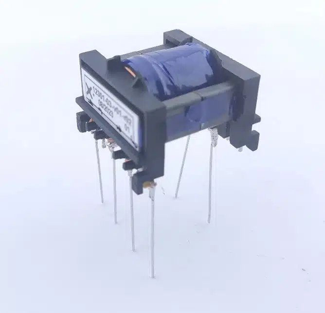
This is how the transformer looked like at the beginning of the experiment:
Then I started the tests, raising the power at the electronic load to reach 60W @ 20V. But, in fact, I couldn’t do it… the flyback controller was shutting down after about 40-45W!
When wondering what had just happened, these were my first ideas:
- I failed selecting the proper turns ratios in the design stage.
- I got confused specifying pinout in Frenetic Online.
- The guys in the lab that built the sample missed something.
After checking the validation sheet that each sample gets and performing some more testing, neither of the ideas mentioned above were true, except one spec! In the validation sheet that I had in front of me, the leakage inductance didn’t match the one in my measurement. To be exact at 60-100kHz range the leakages measured are listed in Table 2.
Note that the leakage inductance is the one of the secondary, as it is measured reflected back to the primary. That is easily done by shorting the secondary and taking an inductance measurement of the primary. The two values are measured at 2 different frequencies, so I couldn’t make a good comparison.
Then I remembered that the controller board mentioned could tolerate up to 5uH of leakage. The original transformer had a leakage inductance of approximately 4.7uH. With 6-7.5uH the design was probably triggering the controller protection, and thus the shutdown after 40-45W.
OK, that might be the reason why. But what’s really happening with leakage inductance? What’s the true value?
Transformer Test Result Evaluation
I took the transformer completely apart and rewind it using round wires. This time I didn’t care for isolation, as functional isolation would be enough. My focus was to make a revision to get the leakage as low as possible and to see if that was the limitation of the test, but also make sure that no mistakes were made in the assembly.
Don’t blame me for not trusting other people in debugging. In these situations I don’t trust anything (not even myself…) that I can’t prove, so I had to make a new sample to eliminate every other possibility. I also ditched the LCR meter and brought the big guns: my frequency response analyser is more than capable to give us a clear idea about the leakage-frequency dependency.
As Archimedes had his “eureka!” (“Εύρηκα” in Greek ) moment, I had mine while setting up the equipment testing! I asked myself: “How did I shorted the secondary winding?”. And my answer was: “Bending those 30mm wires you can see in Figure 1”.
Look at Figure 2. That’s the difference in leakage measured using different lengths of shorting wire at the secondary transformer pins.
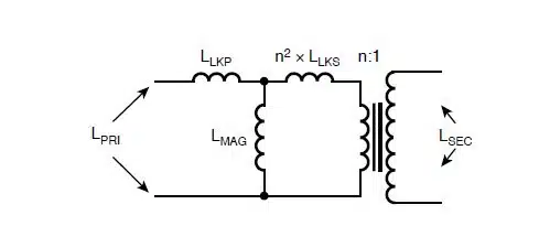
There is a 8.32-5.72 = 2.6uH difference between the two measurements. Let’s prove this! Figure 3. is showing leakage model of an n:1 transformer.
The measured leakage inductance shorting the secondary and taking a measurement on the primary side is:
Where:
- Llkg is the total primary reflected leakage inductance of the secondary (and the primary leakage) – also called lumped inductance.
- Llkp is the primary leakage inductance.
- LMAG is the magnetizing inductance.
- n is the turns ratio of the transformer.
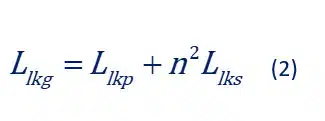
We can simplify (1) with negligible error, noticing the fact that the magnetizing inductance LMAG is 50-60 times bigger than Llkg , then:
In (2) the effect of different lengths of the shorting wire (Llks) result in different Llkg, since the effect of these inductances is magnified n2 = 72 = 49 times. For the 60mm shorting wire:
For the 8mm shorting wire:
What about testing the transformer in the circuit?
As you might have guessed already, when I modified the leads to make sure the secondary pins were soldered directly to the board, everything was working ok, as seen in Figure 4! Extra leakage inductance on the primary side is in the order of 50-100nH because of the wires. Compared to the 5.7uH of the actual transformer inductance that’s an extra leakage ind. of less than 2% (see equation (2)).
Summary and Conclusion
Flying leads on the secondary side when we are talking about a stepdown transformer, as is the case usually with flybacks, can actually “kill” you!
In our case study, just 52mm of extra wire leads of ~52nH of inductance added a 2.6uH inductance looking at the primary side. In flybacks were a leakage goal of 5uH of leakage is reasonable, to minimize the losses on RC snubbers across the primary winding, 2.6uΗ of inductance is a big deal!
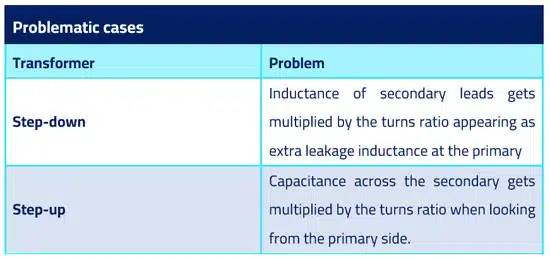
Although, if that was a step-up transformer, then the extra inductance appearing at the primary would be close to nothing. In Table 3 you can see a summary of problematic cases.


